Fluid-Structure Coupling in Water Wedge Impact: Modeling Slamming Effects
540 likes | 674 Vues
This paper explores the fluid-structure coupling methodology applied to the slamming problem encountered when a wedge impacts a free surface. The research addresses the significance of modeling these interactions to improve understanding of fluid dynamics during slamming events. A two-dimensional model is developed using both Lagrangian and Eulerian formulations to accurately capture fluid behavior and structure interactions. The findings include critical pressure dynamics at various wedge angles which have implications for designing marine structures and enhancing safety measures against slamming.

Fluid-Structure Coupling in Water Wedge Impact: Modeling Slamming Effects
E N D
Presentation Transcript
Fluid-Structure Couplingin a Water-WedgeImpact Problem Nicolas AQUELET, Mhamed SOULI, Nicolas COUTY
Plan • What ’s the purpose of this approach? • How to make the modeling? • Fluid-Structure Coupling • Application to Slamming problem • Conclusion
What ’s the purpose of this approach? Why to modelize the impact between a wedge and a free surface? Answer: SLAMMING! But what’s SLAMMING?…
What ’s the purpose of this approach? ?? p x Bibliography: Some theoretical results Assumptions: • 2D Problem : ( x , y , t ) • Rigid wedge • Constant drop velocity • Incompressible and no rotational fluid • No cushioning Free surface a
What ’s the purpose of this approach? Pressure = f(time) for a=30° at a fixed point of the wedge Pressure = f(time) for a=10° at a fixed point of the wedge Bibliography: Some theoretical results Wagner (1932), Zhao et Faltinsen (1993): Asymptotical Approach valid for a < 40° (Mpa) (sec)
What ’s the purpose of this approach? x x y ( ) ( x , y , t ) , V: Constant drop velocity Vt Vt 3 unknowns 2 unknowns at t=t3 p Free surface at t=t2 Free surface at t=t1 Bibliography: Some theoretical results Dobrovol ’skaya (1969), Garabeddian (1953): If infinite wedge , the flow is self-similar
What ’s the purpose of this approach? • Away from the leading edge : • Incompressibility? • Away from trailing edge Free surface when the jet leaves the wedge Bibliography: Some theoretical results Dobrovol ’skaya (1969), Garabeddian (1953): If infinite wedge , the flow is self-similar For a finite wedge, this property is valid away from the edges Free surface at t = 0sec
Plan • What ’s the purpose of this approach? • How to make the modeling? • Fluid-Structure Coupling • Application to Slamming problem • Conclusion
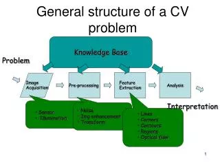
How to make the modeling? Material movement State n State n+1 State n+1 Modeling problems: • Large fluid deformations • Fluid-Structure Interactions Two solutions: Lagrangian Formulation • Lagrangian Modeling of Fluid • Fluid /StructureContact Eulerian Formulation • Eulerian Modeling of Fluid • Fluid/Structure Coupling
How to make the modeling? Lagrangian Formulation Lagrangian Formulation of Navier-Stokes Equations Mass conservation is automatically verified
How to make the modeling? Lagrangian Formulation Modeling of water flow with a Lagrangian Formulation: Strong distortions of fluid meshes
How to make the modeling? Eulerian formulation Eulerian Formulation of Navier-Stokes Equations
How to make the modeling? Intermediate state Split operator : 1st phase : Lagrangian cycle Material movement State n
How to make the modeling? Intermediate state solved by Godunov ’s methods State n+1 Split operator : 2nd phase : cycle of advection Equations of transport
How to make the modeling? Volwater f:Volume Fraction = Volelement Approche Eulérienne multi-matérielle Introduction of a new unknown: the volume fraction air water Intermediate state 0.7 1 Etat n+1
How to make the modeling? ? Volume Fractions for 9 cells are used to compute the slope of the material interface in the centre cell Free surface tracking by Young method (VOF: Volume Of Fluid) air 0.71 0 0 1 0 0.3 1 1 0.5 water
How to make the modeling? Lagrangian Formulation Eulerian Formulation contact >>> Transmission of Interaction forces: structure nodes to fluid nodes Coupling>>> Transmission of Interaction forces: structure nodes to fluid particles
How to make the modeling? Geometric interface Material interface Lagrangian Formulation Eulerian Formulation contact >>> Transmission of Interaction forces: structure nodes to fluid nodes Coupling>>> Transmission of Interaction forces: structure nodes to fluid particles
Plan • What ’s the purpose of this approach? • How to make the modeling? • Fluid-Structure Coupling • Application to Slamming problem • Conclusion
Fluid-Structure Coupling n At t = t , F is added to the forces applied to the fluid particle penetration zoom Computation of the relative distance d = d +(Vs-Vf).dt (here d =0) k n n-1 n F = -k.d n-1/2 At t = t , no yet coupling and the velocity field is computed: Structure Fluid particle at the structure node position zoom Vf Vs n-1
Fluid-Structure Coupling K??? Which K to respect the physical solution of the interaction problem? In theory: the bigger the stiffness K, the smaller the penetration d
Fluid-Structure Coupling However: If the stiffness K is too bigger, the run becomes unstable And: If the stiffness K is too smaller, the penetration becomes unacceptable
Fluid-Structure Coupling n At t = t : n n as af K Ms Mf n n Fs Ff n d Zhong’s work for contact-impact (1993): Defence node Algorithm
Fluid-Structure Coupling Numerical example:Impact of water column water V0 Excepted Pressure in the Eulerian cells near the wall: Rigid Wall
Fluid-Structure Coupling dt=6e-7sec dt=1e-6sec dt=6e-8sec Pressure at the impact for different timestep:
Fluid-Structure Coupling Comparison with a model of reference : V0 V0 Eulerian nodes are blocked Rigid Wall Model with coupling Model of reference
Fluid-Structure Coupling Comparison with a model of reference :
Fluid-Structure Coupling An other numerical Example:Piston Structure V0 V0:constant Fluid
Fluid-Structure Coupling Model of reference Model with coupling V0 is imposed on the Fluid boundary V0 is imposed on theStructure
Fluid-Structure Coupling Comparison with a model of reference :
Plan • What ’s the purpose of this approach? • How to make the modeling? • Fluid-Structure Coupling • Application to Slamming problem • Conclusion
Application to Slamming problem V0=6m/s element 50 Reference theoretical pressure plotted away from the edges 30°
Application to Slamming problem Comparison theory/coupling The results disagree and the numerical curve is perturbed
Application to Slamming problem Comparison theory/coupling by decreasing the time step The results still disagree and the perturbations are stronger than previously
Application to Slamming problem The curves are almost « symmetrical » Comparison of pressures applied on two neighbouring structure elements self-similarity is not respected Influence between the structure element pressures
Application to Slamming problem • Interessant approach: Impulse = momentum transmitted to the structure (by unit area) Impulse: t t 0
Application to Slamming problem Comparison of impulses applied on two neighbouring structure elements Influence between the structure element impulses
Application to Slamming problem A penalty factor is introduced in the Zhong ’s formula: 0<pf<1 The coupling force computed by the Zhong ’s approach seems to be too strong The previous pressure and impulse curves are plotted again by decreasing the penalty factor
Application to Slamming problem Comparison of pressures applied on two neighbouring structure elements pf=0.1 Influence between the structure element pressures
Application to Slamming problem Comparison of impulses applied on two neighbouring structure elements pf=0.1 Influence between the structure element impulses
Application to Slamming problem Comparison of pressures applied on two neighbouring structure elements pf=0.01 Small Influence between the structure element pressures
Application to Slamming problem Comparison of impulses applied on two neighbouring structure elements pf=0.01 Small Influence between the structure element impulses
Application to Slamming problem Comparison of pressures applied on two neighbouring structure elements Self-similarity is respected pf=0.001 Very small Influence between the structure element pressures
Application to Slamming problem Comparison of impulses applied on two neighbouring structure elements pf=0.001 Very small Influence between the structure element impulses
Application to Slamming problem pf=0.001 Comparison theory/coupling with The jet reaches the trailing edge The theoretical and numerical pressures agree
Application to Slamming problem A mesh refinement enables to converge more quickly element 50 element 20 Reference theoretical pressure plotted away from the edges pf=0.001
Application to Slamming problem Comparison of impulses for small penalty factor: The momentum received by the structure changes little
Application to Slamming problem Deformable wedge: Comparison pf= 0.1 / pf=0.01 Von mises stress history Displacement history
Application to Slamming problem Von Mises stress history for pf= 0.1 / pf=0.01