Download
1 / 44
460 likes | 744 Vues
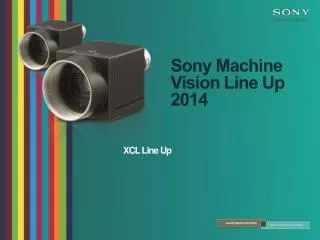
Sony Machine Vision Line Up 2014. XCL Line Up. Product Concept.

E N D
Sony Machine Vision Line Up 2014 XCL Line Up
Product Concept Build and expand over the market-leading Sony XC-HR cubic size analogue camera series, to offer advanced new features and image sensors in digital interface while retaining the HR series DNA and strong mechanical design to deliver unrivalled image quality in a small size, low power consumption camera series that suit all modern Machine Vision applications.
Sony Analogue Cameras Legacy Resolution SXGA XC-HR90 Up to 30 fps XGA XC-HR70 1/3 PS CCD Mono Up to 30 fps XC-ST50CE ½ IT CCD Mono Up to 50 fps XC-ST30CE 1/3 IT CCD Mono Up to 50 fps DXC-390 ½ IT CCD Color Up to 50 fps DXC-390P ½ IT CCD Color Up to 50 fps XC-EI30CE 1/3 IT CCD Mono Up to 50 fps XC-EU50CE ½ IT CCD Mono Up to 50 fps XC-ES51CE ½ IT CCD Mono Up to 50 fps XC-ES30CE 1/3 IT CCD Mono Up to 50 fps SVGA XC-HR58 ½ PS CCD Mono Up to 50 fps XC-ST51CE ½ IT CCD Mono Up to 50 fps XC-ST70CE 2/3 IT CCD Mono Up to 50 fps DXC-990P ½ IT CCD Color Up to 50 fps DXC-990 ½ IT CCD Color Up to 50 fps XC-ES50LCE ½ IT CCD Mono Up to 50 fps XC-ES50CE ½ IT CCD Mono Up to 50 fps XC-EI50CE ½ IT CCD Mono Up to 50 fps XC-56 1/3 PS CCD Mono Up to 30 fps XC-56BB 1/3 PS CCD Mono Up to 30 fps XC-ES30 1/3 IT CCD Mono Up to 60 fps XC-EU50 ½ IT CCD Mono Up to 60 fps XC-EI50 ½ IT CCD Mono Up to 60 fps XC-ES51 ½ IT CCD Mono Up to 60 fps XC-EI30 1/3 IT CCD Mono Up to 60 fps VGA XC-HR50 1/3 PS CCD Mono Up to 60 fps XC-HR57 ½ PS CCD Mono Up to 60 fps XC-ES50L ½ IT CCD Mono Up to 60 fps XC-ES50 ½ IT CCD Mono Up to 60 fps XC-ST30 1/3 IT CCD Mono Up to 60 fps XC-ST50 ½ IT CCD Mono Up to 60 fps XC-ST51 ½ IT CCD Mono Up to 60 fps XC-ST70 2/3 IT CCD Mono Up to 60 fps Technology Interline Transfer Progressive Scan
New SeriesSummary CSeries SSeries • CompactCubicsize29mm Cubic • VGA~5M • Standardsize • 50x50x57.5mm • High resolution
Resolutions & Frame Rates Cubic Frame rate Standard XCL-C30/C 131 fps EXview HAD II XCL-C32/C 104 fps XCL-C130/C 31 fps XCL-S600/C XCL-C280/C 27 fps XCL-S900/C 18 fps XCL-C500/C 15 fps Resolution VGA SXGA Full HD 6 MP 5 MP 9 MP
XCL-C SeriesOverview Profile • VGA to 5 MP • Compact cubic design • CameraLinkPoCL • B&W and Color Main features • 5 image sensors • 1/3” VGA (131fps), 1/2" VGA (104fps) • 1/3” SXGA (31fps), 1/1.8” 2.8M (26fps), 2/3” 5M (15fps) • 8, 10, 12 bit & RGB digital output • Normal, Binning, Partial scan read out • Several trigger modes • Edge detection, pulse width detection, sequential, bulk Design • Picture enhancement functions • Shading & Defect pixel correction • Full auto-Exposure • Gain & Shutter adjustment • Flexible I/O management • Multiple triggers/strobes, PWM • Compact size • 29(W) x 29(H) x 30(D) mm • 3 years warranty
XCL-S SeriesOverview Profile • 6 & 9 MP • Standard size • CameraLink Base • B&W and Color Main features • Exview HAD II CCD • 1” 6 MP (27 fps) • 1” 9 MP (18 fps) • 8, 10, 12 bit & RGB digital output • Normal, Binning, Partial scan read out • Several trigger modes • Edge detection, pulse width detection, sequential, bulk Design • Picture enhancement functions • Shading & Defect pixel correction • Full auto-Exposure • Gain & Shutter adjustment • Flexible I/O management • Multiple triggers/strobes, PWM • Standard size • 50(W) x 50(H) x 57.5(D) mm • 3 years warranty
Image Sensors Overview Sony ICX-424 • 1/3" VGA (640 x 480) HAD CCD @ 130fps • Pixel size: 7.4 x 7.4µm Sony ICX-414 • 1/2" VGA (640 x 480) HAD CCD @ 104fps • Pixel size: 9.9 x 9.9µm Sony ICX-447 • 1/3” SXGA (1280 x 960) EXview HAD CCD @ 31fps • Pixel size: 3.75 x 3.75µm Sony ICX-687 • 1/1.8” 2.8Mp (1920 x 1440) EXview II HAD CCD, 2 ch.@ 26 fps • Pixel size: 3.69 x 3.69µm Sony ICX-625 • 2/3” 5Mp (2448 x 2048) Super HAD CCD, 2 ch.@ 15 fps • Pixel size: 3.45 x 3.45µm Sony ICX-694 • 1/1’’ -6MP (2758x2208) EXview II HAD CCD, 4 ch.@ 27 fps • Pixel size: 4,54 x 4,54µm Sony ICX-814 • 1/1’’ -9 MP (3388x2712) EXview II HAD CCD, 4 ch.@ 18 fps • Pixel size: 3.69 x 3.69µm
Features Highlight New Image Sensors Defect pixel correction Shading correction Temperature readout Special trigger modes Sensitivity Control
New Image Sensors “EXview HAD CCDⅡ” is a trademark of Sony Corporation. The “EXview HAD CCD Ⅱ” is a CCD image sensor that realizes sensitivity (typical) of 1000 mV or more per 1 μ㎡(Color : F5.6/ BW: F8 in 1 s accumulation equivalent) and improves light efficiency by including near infrared light region as a basic structure of Sony’s “EXview HAD CCD”. • Cseries • 1/1.8type2.8M • Sseries • 1/1type6M • 1/1 type9M
EXview HAD CCD II Application Aperture expansion • Increased sensitivity and resolution with same optical format
Defect Pixel Correction Correct the defect pixel of the sensor White defect and black defect ・ ・ ・ ・ ・ ・ ・ ・ ・ ・ ・ ・ ・ ・ ・ ・ ・ ・ Correction ON
Shading Correction Correct the shading of the image by the light conditions and the lens Save the 3 setting values Both B&W and color Shading correctionOff Shading correctionON
Shading Correction Demo Camera + Lens Demo Slanting light Camera + Lens+ LED light
Temperature Readout Temperature sensor installed on front panel PCB Monitor CCD temperature
Temperature Readout ←①What temperature? →②45 ℃ ←③ GPIO-OUT: Hi CL cable GPIO-OUT DC-700 ③ Hi FAN SW BOX ③:FANON 45 degC ② ←Judge temperature 44
Standard Trigger Modes Edge detection Pulse width Configurable trigger delay Configurable trigger delay
Special Trigger Modes Sequential Trigger Bulk Trigger • Sequential Trigger mode 1 2 3 Exposure image Ch 3 Ch 1 Ch 2 Standard triggering 1 2 3 Ch 1 Ch 1 Ch 1 • Bulk Trigger mode 1 Ch 3 Ch 1 Ch 2
Sensitivity Control Wavelength :~380nm UV: Ultra Violet ⇒Surface check Wavelength : 380nm~760nm “Visible area” Wavelength :760nm~ IR:Infrared ⇒ Internal check
Sensitivity Control CCD substrate bias voltage adjustment • By adjusting the substrate bias, the saturation signal charge can be increased or decreased • Increasing the saturation signal charge improves the sensitivity • Decreasing the saturation signal charge reduced the smearing • Dynamic control by software command Smear Smear reduction Sensitivity improvement
Other Feature Partial scanning Pixel binning Auto Exposure Lookup Table Memory channel Flexible GPIO
Parameter: “Offset X” Parameter: “Width” Parameter: “Offset Y” Parameter: “Height” Partial Scanning High speed acquisition (Partial Scan) • By reducing the size of the acquisition region (ROI) the amount of data can be reduced and the acquisition speed increased • Can be used in combination with H/V binning function • Vertical: 2[pix] step / Horizontal: 2[pix] step Four parameters
Pixel Binning Combines 2 pixels together with the following benefits • Sensitivity increase • Readout noise reduction • Data reduction with same field of view • Frame rate increase with vertical binning • Available for B&W models only Example: XCL-C280 2.8MP @ 26 fps (max)
Illustration of response speed adjustment Auto Exposure Combines Auto Gain and Auto Shutter control • Auto Gain only / Auto Shutter only / Auto Exposure (Gain + Shutter) Operations • Dark: increase shutter time until Max Shutter then increase Gain • Bright: decrease Gain until Min Gain then decrease shutter time Parameters • Same target luminance value (14bit) • Same detection area • Max / Min Gain adjustable • Max / Min Shutter speed adjustable • Adjustable response speed
Lookup Table (LUT) • LUT:Transform the input data into more desirable output format • Input signal (luminance signal) • Output signal (Digital data) • Look Up Table • 4 presets setting • ★Mode • ⑤ User setting • (IN:12bit、Out:12bit) • ④Linear interpolation • ③ Binarization • ② Negative • ① Linear(default)
0 :Default setting(default at exfactory) 1 :Gain:0,Shutter:1/100s,・・ 2 :Gain:9, Shutter :1/30s,・・ 3 :Gain:0, Shutter:1/10000,・ 4 : 5 : ・ ・ 15: Memory Channels Save the camera setting *Gain, Shutter, White Balance, etc. *1(default setting) +16 settings (CameraLink,GigE Vision) FPGA ADC μC IO
User Settings Memory Channels • 16 Memory Channels are provided for storing user’s camera settings • All camera parameters saved (incl. interface settings) • Boot-strap register define which channel is loaded on startup • Non-volatile memory User Memory (tentative name) • Arbitrary user data can be stored • Calibration settings & Camera ID • Licensing information • Non-volatile memory • 32 kbytes + 64 bytes x 16ch • Lockable memory area • Password protected
GPIO Overview Input Pins Features • Trigger IN / Trigger counter / Counter reset / GPO Output Pins Features • Strobe OUT / Pulse Width Modulation (PWM) / GPI Serial Interface • UART over GPIO Flexible GPIO management • All pins can be used in one of the above modes independently • Polarity change support
Strobe Outputs Management Multiple Strobe Outputs • Three(3) configurable strobe outputs (pulse width and delay) • Pulse Width Modulation (PWM) • Analogue voltage control trough digital I/Os and LED lighting intensity control w/o additional external device Arbitrary control or latched to Exposure Output • Control of complex lighting without additional external devices
Appendix Mechanical & environmental specifications Camera Link Interface XCL-C series specifications summary XCL-S series specifications summary
Mechanical Interface Backward Compatible with XC-HR and XC-E series (XCL-C) • Same optical axis position • Same or higher image sensor mounting accuracy • Same mounting holes positions • Bottom: 4 x M2, 3 x M3 / Top: 2 x M2 Screw Lock Connectors • Standardized mini-PoCL screw lock connector (SDR-26)
XCL-C Series Mechanical & Environmental Specifications Shock Resistance • 70G Vibration Resistance • 10 G (20 to 200Hz) Operating Temperature • -5 to +45°C External Power Supply • PoCL: + 9V to 15 V Power consumption • PoCL: 3.2 W (max) • Mass • 56 g (2.0 oz) • Temperature Sensor • Installed on front panel PCB
XCL-S Series Mechanical & Environmental Specifications Shock Resistance • 70G Vibration Resistance • 10 G (20 to 200Hz) Operating Temperature • -5 to +45°C External Power Supply • + 10.5V to 15 V Power consumption • PoCL: 5.5 W (max) • Mass • 200 g (7.1 oz) • Temperature Sensor • Installed on front panel PCB
Camera Link Interface Camera Link Base Configuration • Single PoCL connector • Up to 1.923Gbps of bandwidth Multitap transfer • Support single(1) tap and dual(2) tap transfer • Reduced clock in dual tap mode allow longer cable length Real Time Signaling • Frame Valid (FVAL), Line Valid (LVAL), Data Valid (DVAL) • Allow full control over camera timings Ex. 2.8Mp @ 26fps: 1 tap (81MHz), 2 tap (40.5Mhz)