Intelligent Computer Solutions
Intelligent Computer Solutions.


Intelligent Computer Solutions
E N D
Presentation Transcript
Intelligent Computer Solutions ICS is a widely known and well respected industry leader in the field of Computer Forensic Data Acquisition. In the mid-nineties ICS introduced innovative Forensic tools based on its patented technology of capturing data at high speeds. During this period ICS has used it’s experience to developed new generation Forensic data acquisition tools to help Law Enforcement fight today’s high-tech computer-based crimes. The Forensic products developed by ICS have been designed as a result of close consultation and cooperation with various Law Enforcement Agencies in the U.S. and other parts of the world.
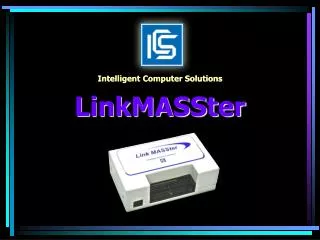
Forensic Tools Intelligent Computer Solutions RoadMASSter-II SOLO-3 DriveLock FW/USB LinkMASSter-II
Technical Review • Hard Disk Interfaces • Hard Disk Transfer Protocol • Hard Disk Drive Physical Structure • Hard Disk Drive Logical Structure • Hard Disk Drive Performance Factors • Hard Disk Drive Hashing
DriveLocks DriveLock IDE Firewire/USB DriveLock in a Caddy
Overview Designed exclusively for Forensic applications, the DriveLock Firewire/USB device provides a secure hardware write block protection solution for viewing or analyzing an IDE hard drive without the possibility of modifying any evidence data. The device is designed to block write operations directed to IDE drives through the Firewire/USB interface. Disk drive write operations exist in two categories: Command and Data Drive lock does not affect Command-write operations. The device has electronic circuitry that can distinguish between these two operations and effectively block only data writes. This capability is guaranteed not to cause corruption to the data on the drive being blocked. ATA Specifications Drive Lock will recognize and prevent all disk writes that are represented and documented in all ATA specifications up to and including version 7. For example, DMA operations that are queued, extended and streamed will be recognized and prevented. Drive Lock will work equally well with legacy (old) drives as well as with the newest Ultra-DMA 100 and 133 drives.
Firewire/USB Overview Connects through Firewire 1394-B or USB 2.0 or 1.1 Small size (4”W X 3”D X 1”H) allows for complete portability and ease of use in the field IDE ports for both “desktop IDE” (3.5”) and “laptop IDE” (2.5”) media.
System Requirements Windows 98, ME, 2000 or XP (latest Service Packs are recommended for each operating system) Pentium processor or equivalent 64 megabytes of RAM (256 MB recommended) Available FireWire-A/B or USB (1.0 or 2.0) port
Device Connectors Power Switch Power LED HDD Status LED Suspect’s HDD Power Cable 40 Pin IDE for 3.5” hard drive 44 Pin IDE for 2.5” Notebook hard drive Pin 1 BACK Power Connection Firewire-B Connections USB 1.1/2.0 Connections
Hardware/Software Installation • Make sure the Firewire/USB device is powered off. • Connect DriveLock Firewire/USB to your computer using the appropriate supplied Firewire or USB cable. • Attach the Suspect’s drive to the DriveLock Firewire/USB port using the appropriate cables. • Configure the Suspect’s drive as a master drive. • Connect the HDD power cable to the Suspect’s drive and to the device. The HDD power cable is not required for 2.5” laptop drives since power is fed through the 2.5” interface connector. • Connect the unit’s external power supply. • Power on DriveLock Firewire/USB device. Windows will detect new hardware when the device is first installed and will display its “Add Hardware Wizard”.
Power and Status LEDs • The DriveLock Firewire/USB device has two LED indicator lights that provides status of the unit’s operation and is helpful in troubleshooting DriveLock Firewire/USB related problems. • The Status LED indicates hard drive activity with the DriveLock Firewire/USB device. This light will flash red to indicate that the drive is operating normally. It is not uncommon for the light to stay constantly lit during an acquisition. • The Red Power LED indicates that the device is powered ON. • NOTE: In the event that the LEDs do not respond properly, it may indicate that the device hardware or attached drive is not properly connected. The unit itself may be defective but there is no risk that the subject media will be written to, although the unit may fail to allow the operating system to recognize the drive.
Installing Windows 2000/XP Drivers 1. Click [Next >] when the Add Hardware Wizard launches
Installing Windows 2000/XP Drivers 2. Choose the option “Search for a suitable drive for my device (recommended)” and click [Next >]
Installing Windows 2000/XP Drivers 3. Remove any check marks in any of the boxes, and click [Next >]
Installing Windows 2000/XP Drivers 4. Click [Next >] when the summary screen appears
Installing Windows 2000/XP Drivers 5. Click [Yes] to install the driver
Installing Windows 2000/XP Drivers 6. You will now see the summary screen that identifies that DriveLock Firewire/USB is properly installed.
Installing Windows 98 USB Driver 1. Download the Windows 98 USB Driver onto a floppy disk. You can obtain the driver by clicking on Downloads DriveLock DriveLock Firewire/USB USB Driver for Win98 drivers from the ICS website at www.icsforensic.com 2. Click [Next >] at the add new hardware wizard.
Installing Windows 98 USB Driver 3. Choose “Search for the best driver for your device” and click [Next >]
Installing Windows 98 USB Driver 4. Choose “Floppy Disk” and insert the disk containing the driver you downloaded from the ICS web site into the floppy drive. 5. Click [Next >]
Installing Windows 98 USB Driver 7. Click [Finish]; this signifies that DriveLock Firewire/USB is now properly installed.
Installing Windows 98 USB Driver 6. Click [Next >] at the Summary screen
Hot Swapping Drives with DriveLock FW/USB 1. To hot swap (remove) a Windows mounted drive attached with USB or Firewire, first right click the plug and play insertion icon 2. Highlight DriveLock Firewire/USB (shown here as a USB Mass Storage Device) and click [Stop]
Hot Swapping Drives with DriveLock FW/USB 3. On the confirmation screen, highlight the parent device (not the individual volumes) and click [OK]
Hot Swapping Drives with DriveLock FW/USB • Power off DriveLock Firewire/USB device. • Disconnect the Suspect’s drive from the device. • Attach another Suspect’s drive and power ON the DriveLock Firewire/USB device. • 7. After a period of a few seconds, Windows will redetect the new drive and automatically load the appropriate drivers.
Trouble Shooting The DriveLock Firewire/USB device will not work with Operating Systems that do not support USB or FireWire such as Windows 4.0 or DOS. Check that the power switch is turned ON and that the power supply is connected. Check the hard drive manufacturers’ web site for HDD Master/Single configuration. Make sure the drive is jumpered for master/single operation. Make sure the Standard 2.5” data cable’s Pin-1 is properly aligned with the drive’s Pin-1 connector and the device’s Pin-1 connector. If the Standard 2.5” data cable is attached properly and the drive is not powering ON., try using an external 3.5” to 2.5” HDD adapter and use the unit’s IDE interface data connector to connect the 2.5” Notebook drive. If the Suspect’s drive fails to power ON, try testing the device with a different drive to eliminate a power supply issue with the unit.
Special Features • Connects to 2 1/2 inch and 3 1/2 inch drives. • Can be used in both PIO and Ultra DMA modes up to ATA-7. • Appears completely transparent to the computer. • No external power supply required. • Prevents unwanted data writes. • Functions with PC or IMSOLO II/III. • Easy to use. • No special software needed.
Hardware IDE drive cable connection
PC Setup • Use the following procedure to set up the Drive Lock device using a PC: • Open the PC’s cover. • Connect the ICS supplied 36” UDMA cable connector to the Drive Lock IDE connector. Connect the loose end of the UDMA cable to the PC’s secondary IDE controller. • Connect the ICS supplied 36” power cable to an available PC power connector. Connect the loose end of the power cable to the Drive Lock power connector. • Connect the ICS supplied 6” UDMA IDE data cable connector to the Drive Lock IDE connector. Connect the loose end of the UDMA IDE cable to the Drive Lock hard disk drive. • 5. Connect the ICS supplied 6” power cable to the Drive Lock power connector and connect the loose end of the power cable to the hard disk drive.
PC Setup with PCI IDE Controller • To set up the Drive Lock device using a personal computer and a PCI IDE controller, use the following procedure: • Open the PC’s cover. • Connect the ICS supplied PCI IDE controller card to an available PCI slot. • Power ON the PC and Install the supplied PCI IDE controller card’s drivers. • Power OFF the PC. • 5. Connect the ICS supplied 36” UDMA cable connector to the PCI IDE controller card’s external IDE connector. • 6. Connect the ICS supplied 36” power cable to an available PC power connector. • 7. Follow PC Setup steps 3, 4 , and 5.
Overview Designed exclusively for Forensic applications, the LinkMASSter-2 is a fast and effective solution to seize evidence data from an un-opened PC or notebook, using the Firewire or USB interface. This compact unit is a high-speed Forensic data acquisition tool designed for caputering data from a Suspect’s hard disk drive to an external “Evidence” hard disk drive without corruption as a result of the duplication process. Transfer rates can exceed 3 GB/Min depending on the interface used and the Suspect’s PC/Notebook performance.
Features • Easy-to-use, portable system. • Transfer rates can exceed 3 GB/Min. • Supports capturing from SCSI, IDE and Serial-ATA drives. • Seize from any Intel-based or compatible Suspect’s notebook or PC that has native USB 1.1/2.0, IEEE 1394-B or a 32-Bit Cardbus port. Compatible with USB 1.1/2.0, IEEE 1394A/B (I. Link, FireWire). • Uses a Bootable application CD which write protects internal Suspect’s drive. • Copies software loads independent of the suspect’s operating system. • Offers a simple graphical menu driven interface. • Save your configuration setting with our new Load and Save Config option • Offers flexible Capture modes such as “LinuxDD”. • Intelligent Copy that seizes data areas only. • Offers multiple hashing methods such as CRC32, SHA1, and MD5 during data seizure. • Provides detailed drive information of Suspect’s HDD. • Provides a high-speed drive “sanitizing” solution, clearing Evidence drive of all data. • Offers audit trail print capability.
Definitions • Audit Trail - Provides a hard copy containing detailed information about the operation performed. • Evidence (Destination) Drive - The "Evidence Drive" refers to the destination drive. This is the • Drive that is used to transfer or seize data to. • Suspect (Source) Drive - The "Suspect Drive" refers to the source drive. This is the drive that is used to seize data from. • Hash Calculation - Hashing is a process that calculates a "unique signature" value for the contents of an entire drive. • Message Log - Contains a record of the events performed for a given operation. • Multiple Capture (Linux DD) Linux DD format is a method of capturing a suspect drive where the entire image of the suspect drive is saved in one or several separate files (fragments) inside a FAT32 partition on the Evidence drive. If the partition does not exist, it will be created and scaled to the drives capacity. The subsequent captures will be stored in the same partition. Each capture operation will be written into a separate subdirectory. • The file size of each fragment is 640Mbytes so that the fragments can be burned onto CDs. Each fragment contains the suspect drive sector data without any compression or header type information. Thus the first fragment will contain the first 640Mbytes of sectors from the suspect drive, the second fragment will contain the next 640Mbytes and so on. Each fragment will referenced using the case name with file extensions 001, 002, etc. • Intelligent Copy (IQCopy)– Intelligent Copy mode is a method of capturing a suspect data areas only and skipping blank sectors.
Definitions • Read-Back Verification - Enabling the Read-Back-Verification option causes a unit to read back each byte written to a Evidence drive, and to verify it against the corresponding byte in the suspect drive. • Single Capture (100%) - In this mode the suspect drive will be copied sector by sector to the evidence drive. Block zero of the suspect drive will be written to block zero of the evidence drive and so on. The evidence drive can contain a maximum of one captured image when the Single Capture operation is selected. • Wipeout DoD - The Wipe Out DoD operation is designed to meet U.S. Department of Defense specification DoD 5220-22M regarding the sanitization of hard drives. • Wipeout Iterations - Each iteration makes two write-passes over the entire drive: • - The first pass inscribes ONEs (1) over the drive surface (in hex: 0xFF). • - The next pass inscribes ZEROes (0) onto the surface (in hex 0x00). • Wipeout Pattern - The value written to each byte of each sector on the Evidence (Destination) drive during a WipeOut operation. • Wipeout Remainder - When enabled, this setting instructs the operation to sanitize the "remainder of the evidence drive" during a capture operation. The area of the "remainder of the evidence drive" is considered to start from the last sector of the suspects drive.
System Requirements Table 3. System Requirements System Specifications Table 2. System specifications
Chapter 2: Hardware Inventory Table 1. Quick-Reference Parts List
Hardware Description This section provides a parts list and a description of the hardware supplied with the LinkMASSter-2. Power Switch Power and Status LED Standard IDE HDD Connector 2 ½” Notebook HDD Connector Figure 6 Drive Interface Panel HDD Power Output Port
LinkMASSter-2 Port Interface Panel HDD Power Cable UDMA Data Cable FireWire-B Ports 1 and 2 Power Input Port USB 1.1/2.0 Port FireWire-B Cable Power Adapter Cord
Hardware Setup • Connect the ICS supplied UDMA data cable connector, labled “IM Unit Side CONN” to the unit’s IDE connector. Connect the loose end of this cable, labeled “HDD Side CONN” to the Evidence (Destination) drive. • Connect the ICS supplied HDD Power cable to the LinkMASSter-2 HDD power connector which is located next to the IDE connector. Connect the loose end of this cable to the Evidence drive’s power connector. • If using the FireWire 1394 interface, connect the ICS supplied FireWire 1394-B cable to a FireWire A/B port. If using the USB interface, connect the ICS supplied USB cable to the USB port. Connect the loose end of this cable to the corresponding interface on the Notebook/PC
Hardware Setup Continuted Connect the unit’s power supply and turn ON the unit. The power LED will turn ON indicating that the unit is powered ON. Configure the Notebook/PC BIOS to boot from the CD Drive NOTE: Various Notebook/PC BIOS setup requires deferent key combinations at boot up to change the default Device Boot Order. It is the user’s responsibility to correctly perform this setup CAUTION: Allowing the Suspect’s computer to boot from its internal hard drive may result in lost or modified Suspect data.
Software Setup using the LinkMASSter Bootable CD • Verify that the hardware is properly configured. • Verify that the LinkMASSter-2 is powered ON. • Insert the LinkMASSter Bootable CD1. • Power ON the Notebook/PC. • The LinkMASSter application menu will be displayed indicating the drives detected • Select Suspect drive to seize from in the list of drives provided. • Select the Evidence drive to seize to
7. Select Multiple Capture, Single Capture or Intelligent Copy Mode. • Select the Program Settings tab and verify the settings in the program settings window. • Press the Start button to start the operation. • After the operation completes, eject the LinkMASSter bootable CD, power OFF the computer and LinkMASSter-2, and then disconnect the Evidence drive.
The LinkMASSter provides an easy to use menu driven graphical user interface. This interface allows the user the ability to set up and perform the available functions. Refer to this chapter for a description of functions and for detailed usage. The graphical user interface (Figure 8) is divided into six program tabs: Main, Case Information, Program Settings, Printer Settings, Status and About. There are also some command buttons and a Message window. Main Menu Command Buttons Message Window • Figure 8. LinkMASSter Interface
Command Buttons Drive Info: Displays information about Suspect and Evidence drives in the Message Window. Print Log: Prints the content of the Message Window to the configured printer. Save Log: Saves the content of the Message Window to a USB memory stick, flash card or to floppy disk. Load Config: Loads your LinkMASSter configuration from a USB memory stick, flash card or from floppy disk. Save Config: Saves your LinkMASSter configuration to a USB memory stick, flash card or to floppy disk. Start/Abort: Used to Start or Abort the operation. Exit: Used to Closes the application. Message Window: Used to display event log information.
Main Program TabFunctional descriptions of menu items are discussed in the following sections. The Main Tab allows selecting the operation to be performing and which drive(s) will be used for the operation. The following settings are available: Source (Suspect) Drive Select the Suspect drive, from the list of drives detected by the software. Destination (Evidence) Drive Select the Evidence drive, from the list of drives detected by the software.
Operations Mode • Multiple Capture – Linux DD Format • Single Capture - 100% • Intelligent Copy Mode • Wipe Out Destination Drive • Hash Verification
Case Information Tab Investigator Name Investigator Title Investigator Number Operation Date Operation Time Case Name Case Number Evidence Number BIOS Date & Time Case Number Evidence Number BIOS Date & Time Seizure memo Suspect name Witness Name 1 Witness Name 2 Comments Enter any comments View Folders Button