Download
1 / 53
550 likes | 792 Vues
Simple Machines and Mechanical Advantage. Definitions. Energy:. Ability to do work. Work= . Force x Distance. Force:. A Push or a Pull. Work input and output. Work input is the amount of work done on a machine. Input force x input distance

E N D
Definitions Energy: Ability to do work Work= Force x Distance Force: A Push or a Pull
Work input and output • Work input is the amount of work done on a machine. • Input force x input distance • Work output is the amount of work done by a machine. • Output force x output distance Wout = Win Fout x Dout = Fin x Din 10N x 3m = 2N x 15m 15 m Din Dout 3 m Fin 10 N
The 6 Simple Machines Screw Wedge Inclined Plane Pulley Wheel and Axle Lever
Inclined Planes • An inclined plane is a flat surface that is higher on one end. • Inclined planes make the work of moving things easier
The Inclined Planea sloping surface that does not move • An inclined plane provides for NOT Less work but less effort. • The trade off is greater distance to travel. • Used to reduce the force needed to overcome the force of gravity when lifting or lowering a heavy object
Inclined Plane The Egyptians used simple machines to build the pyramids. • They built a very long incline out of dirt that rose upward to the top of the pyramid very gently. • The blocks of stone were placed on large logs (wheel and axle) and pushed slowly up the long, gentle inclined plane to the top of the pyramid.
Inclined Plane Inclined Plane
Inclined Plane -Mechanical Advantage • The mechanical advantage of an inclined plane is equal to the length of the slope divided by the height of the inclined plane. • While the inclined plane produces a mechanical advantage, it does so by increasingthe distance over which the force must move.
The Levera rigid bar that is free to turn about a fixed point called the fulcrum Every Lever has three (3) parts: 1. Resistance Force, Input Force or Load • What you are trying to move or lift. 2. Effort Force or Output Force • The work done on the Lever. 3. Fulcrum • A fixed pivot point.
First Class Levers • The fulcrum is midway between the effort and the load: • there is NO change in force, speed or distance Effort LOAD Fulcrum
First Class Levers The fulcrum is between EF (effort) and RF (load).Effort moves farther than Resistance.Multiplies EF and changes its directionThe mechanical advantage of a lever is:the ratio of the length of the lever on the applied force side of the fulcrum to the length of the lever on the resistance force side of the fulcrum.
First Class Levers • The fulcrum(fixed pivot point) is located between the effort (input) and the resistance (output) Forces. • The effort and the resistance move in opposite directions. • The effort force pushes down in order to lift the resistance (or load.)
Examples of First Class Levers • Crowbars • Scissors • Pliers • Tin snips • Seesaws
Second Class Levers • The load is between the effort and the fulcrum. • The fulcrum is at one end of the lever. • The fulcrum is usually closer to the load. • Second class levers produce a gain in force.
Second Class Levers RF (load) is between fulcrum and EF.Effort moves farther than Resistance.Multiplies EF, but does not change its direction.The mechanical advantage of a lever is:the ratio of the distance from the applied force to the fulcrum to the distance from the resistance force to the fulcrum.
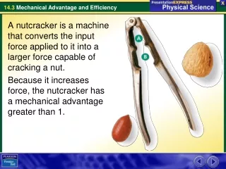
Examples of Second Class Levers • Wheelbarrow • Bottle opener • Nutcracker • Door
Third Class Levers • The effort is between the load and the fulcrum. • There is usually a loss in force, but a gain in speed and distance.
Third Class Levers EF is between fulcrum and RF (load) Does not multiply force Resistance moves farther than Effort.Multiplies the distance the effort force travelsThe mechanical advantage of a lever is: the ratio of the distance from the applied force to the fulcrum to the distance of the resistance force to the fulcrum.
Examples of Third Class Levers • Broom • Shovel • Fishing rod • Tweezers • Hammer • Arm
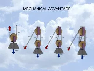
The Pulleya wheel that turns around an axle • A pulley is a grooved wheel that turns around an axle (fulcrum), and a rope or a chain is used in the groove to lift heavy objects. • A pulley may be fixed, moveable, or used in combination.
Pulleys • Pulley are wheels and axles with a groove around the outside • A pulley needs a rope, chain or belt around the groove to make it do work.
The Pulley • A pulley changes the direction of the force: • Instead of lifting up, you can pull down using your body weigh against the load (what is being lifted) • A pulley gains nothing in force, distance or speed.
The Pulley • A moveable pulley acts as second class lever. • The load is between the fulcrum and the effort EFFORT FULCRUM LOAD
The Pulley • A compound pulley is a system of movable pulleys. • Mechanical advantage can be increased by using more than one pulley.
Diagrams of Pulleys Fixed Pulley A fixed pulley changes the direction of a force; however, it does not create a mechanical advantage. The mechanical advantage of a moveable pulley is equal to the number of ropes that support the moveable pulley. Moveable Pulley
The Fixed Pulley • Is attached to something that doesn't move such as the ceiling or wall) • It acts as a first class lever with the fulcrum located at the axis • Instead of a bar the pulley uses a rope or chain.
The Combined Pulley • The effort needed to lift the load is less than half the weight of the load. • The main disadvantage is it travels a very long distance.
The Wheel & Axlea wheel connected to a rigid pole • The wheel & axle is a modified lever. • The center of the axle acts as a fulcrum, making the wheel a lever that rotates around in a circle.
WHEEL AND AXLE This axle is stuck rigidly to a large wheel. Fan blades are attached to the wheel. When the axle turns, the fan blades spin.
Wheel and Axle The mechanical advantage of a wheel and axle is: • In the wheel and axle illustrated above, the radius of the wheel is five times larger than the radius of the axle. Therefore, the mechanical advantage is 5:1 or 5. • The wheel and axle can also increase speed by applying the input force to the axle rather than a wheel. This increase is computed like mechanical advantage. This combination would increase the speed 5 times. the ratio of the radius of the wheel to the radius of the axle. 5 1
GEARS-Wheels and Axles Each gear, in a series, reverses the direction of rotation of the previous gear. The smaller gear will always turn faster than the larger gear.
Gear Ratio When two gears are meshed, one gear is driving the other gear (the driven). Gears cause multiple changes: • speed • direction of motion • turning forces DRIVER DRIVEN
Gear Trains The mechanical advantage of a gear train is calculated by dividing the number of teeth of the driver gear by the number of teeth of the driven gear. DRIVER DRIVEN In the example on above, the mechanical advantage is 12:8 or 1.5 to 1 so the small gear rotates three times for every 2 rotations of the large gear.
The Screwan inclined plane wrapped around a central cylinder • A Screw has two (2) parts: • The Body – Cylinder Post • The Thread – Inclined Plane wrapped around the cylinder.
The Screw The mechanical advantage of an screw is calculated by dividing the circumference by the pitch of the screw. The pitch of a screw equals 1/ number of turns per inch.
Functions of the Screw • To fasten things – the standard screw or nuts & bolts. • Drill bits are screws used to make holes. • A jackscrew is used to lift heavy objects; car jack.
The Screw • When you turn a screw: • the input force is changed by the threads into an output force. • the output force pulls the screw into the materials. • friction between the threads & the material holds the screw in place.
The Wedgetwo inclined planes, joined back to back, that taper to a sharp edge • Awedge is used to increaseforce. • A wedge changes the direction of the input force. • The material remains in place while he wedge moves through it. • Wedges can be used to split, cut or fasten. • Wedges can be forced between two things to hold them tightly together, like nails or a doorstop.
The Wedge • The mechanical advantage of a wedge can be found by dividing the length of either slope (S) by the thickness (T) of the big end. S • For example, The length of the slope is 10 inches and the thickness is 4 inches. The mechanical advantage is equal to 10/4 or 2.5. As with the inclined plane, the mechanical advantage gained by using a wedge requires a corresponding increase in distance. T