Download
1 / 15
150 likes | 269 Vues
Summary of the technical stop activities on collimators (w17, 2012) . O . Aberle – 07/05/12. Main activities during the last technical stop. TDI.4R8 Collimator roller screw replacement TIM intervention / observations. TDI.4R8.

E N D
Summary of the technical stopactivities on collimators (w17, 2012) O. Aberle – 07/05/12
Main activitiesduringthe last technicalstop • TDI.4R8 • Collimatorrollerscrewreplacement • TIM intervention/observations O. Aberle – CWC
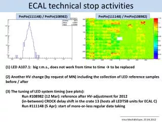
TDI.4R8 • TDI.4R8: New x rays have been taken on:Up and downstream beam screen – transition – jaw extremity. • Result: No change since the last scan in January. Stable conditions after the 144 bunches dumping. • The parking settings of TDI.4R8 should be changed from 37 to 55 mm during physics, as in Pt. 2. O. Aberle – CWC
TDI.4R8 • Result: No change since the last scan in January. Stable conditions after the 144 bunches dumping. • The parking settings of TDI.4R8 should be changed from 37 to 55 mm during physics, as in Pt. 2. 25.04.2012, tube 25.04.2012, source 25.01.2012, source O. Aberle – CWC
Looking at the 2 LVDTs (RU-RU2) 2012 intensity RU2 RU Clear symmetric drift of the 2 LVDTs indicating a possible deformation of the right jaw of TDI in point 8. TDI observations and beam measurements, C. Bracco 130th LMC Meeting held on 25 April 2012 O. Aberle – CWC
Looking at the 2 LVDTs (RU-RU2) 2012 intensity RU2 RU 2011 intensity RU Same LVDT feature in 2011 and 2012. However, not seen in 2011, as limits were twice larger (0.5s) than in 2012 (0.25s). TDI observations and beam measurements, C. Bracco
Conclusion • We see a drift of the TDI LVDTs mainly during physics jaw position outside interlocks (±0.25 s) when back at injection setting (already observed last year but tolerances more relaxed) • Symmetric drift for the 2 LVDTs located at the 2 sides of the motors jaw deformation? • Measurements with beam indicate a possible deformation towards the beam (“safe” side) of the order of 0.5 s • Angular scan on the cold jaw did not show any evident change. • Not always clear correlation between LVDT drift and beam condition need more statistic • Not clear correlation between LVDT drift and jaw deformation need reference measurement with cold jaw (right after TS, no angular scan) repeat measurements with warm jaw (including angular scan) • Once we define if and by how much the TDI jaw is deformed and the correlation LVDT/jaw setup thresholds accordingly to insure protection in case of miss-injection (TDI grazing) • Still to be understood the cause of the warming up when the jaws are at 55 mm (high order modes?), are we heating the jaw or the full structure? (N.B. after opening TDI jaws from 20 mm to 55 mm vacuum improved but there was no clear evidence of improvements in heating………) TDI observations and beam measurements, C. Bracco 130th LMC Meeting held on 25 April 2012 Works ongoing!! O. Aberle – CWC
Collimatorrollerscrewreplacement • Elogbook22/04/2012 00:16:45 22/04/2012 00:46:43 00:29:58 • Collimator Hardware TCSG.5L3.B1 Collimator stuck; won't drive to injection settings. - The TCSG.5L3.B1 failed to go correctly to injection settings after the collimator setup ( suspected problem with roller screw), and required piquet reset. Normally this collimator should not be included in the active set until the hardware problem is fixed. • Performance loss on axis B. First steps lost during the week end, recovery with simple resetting. Within 3 days the situation was degrading a lot. The axis, and therefore the collimator had to be disabled in parking position after regularly loosing steps. • This triggered a systematic sound check with the TIM in point 3. The noise profile off all 16 out of 18 collimators have been registered, a list of conspicuous collimators has been delivered for further inspection. • In parallel, torque measurements have been performed on most of the collimators, in reducing the motor current until steps are lost. • These values have been compared with original data taken during commissioning campaigns. • All suspicious collimators have been checked and validated for operation in situ. O. Aberle – CWC
Collimatorrollerscrewreplacement • The roller screw on TCSG.5L3.B1 had to be replaced due to mechanical wear. There is a clear correlation between a high torque value and the noise pattern. • "SEM observations and EDS analyses of debris found in a roller screw from a LHC TCS collimator table“https://edms.cern.ch/document/1212253/1 • The roller screw is still in the RP buffer zone and will be analysed as soon as possible. • A second roller screw was found, based on the noise recording. The torque measurement did not yet indicate problems. • Affected is the axis A on the TCP.6R3.B2. The screw showed signs of wear and was exchanged preventively. • Collimators in Pt. 3, 5, 7 and 8 have been crosschecked with visual inspection. No further case has been found. • All collimators are commissioned and ready for operation. O. Aberle – CWC
Collimatorrollerscrewreplacement Dustanddebris in the end capandthehousing Some dry screwsregreased O. Aberle – CWC
Collimatorrollerscrew check In combination of acoustic check and torque measurement a good indication for problems can be found, but: TCP.6R3.B2 not detectedwithtorquemeasurement O. Aberle – CWC
Collimator with the problem O. Aberle – CWC
TIM intervention • Set up and tuning of TIM in Point 3: ~ 5 h.This can be faster with final parameters, around 2 h. • Sound recording of 16 collimators during 6 h (night, no access). • Remote control from the CCC with data analysis in parallel. • Visual inspection with camera will be useful in the future. O. Aberle – CWC
TIM exercise - Sound inspection of the collimators in S34 (23/24 April 2012) EN/HE - EN/STI Collaboration Microphone Faulty (the initial one): TCSG.5L3.B1_L_IN_OUT Normal: TCLA.A5R3.B1_L_IN_OUT TCP.6L3.B1_L_IN_OUT Courtesy R. Folch, B. Feral Suspicious: TCP.6R3.B1_L__IN_OUT O. Aberle – CWC Roller screw
Outlook • Improve the sound and image quality for the TIM, very powerful tool for the future. • Reference sound recording of all collimators. • Improve the accessibility to the screw (cap). • A regular check during long breaks and shut-downs with re-lubrication of the screw. • Automatic motion cycles during LS1 to be planned. O. Aberle – CWC