Full Order Observer Design Using Simulink
Full Order Observer Design Using Simulink. David Pyne EE 692. Goal of the Project. To design a Simulink library block that automatically generates a Full Order Observer for a given linear dynamical system Desired Characteristics: Scaleable Practical Easy to Use. Agenda.


Full Order Observer Design Using Simulink
E N D
Presentation Transcript
Full Order Observer Design Using Simulink David Pyne EE 692
Goal of the Project • To design a Simulink library block that automatically generates a Full Order Observer for a given linear dynamical system • Desired Characteristics: • Scaleable • Practical • Easy to Use
Agenda • What is a Full Order Observer? • Overview of Linear Dynamical Systems • Library Block Concept • Design of the Observer • Simulink Implementation • A Simple Example • A More Complex Example • Questions
What is a Full Order Observer? • A mathematical model of the entire dynamical system • An estimator of the unmeasurable states • Flexible • Scaleable • Highly accurate
x1 y1 MIMO . . . . . . xn ym Overview of Linear Dynamical Systems • Systems characterized by the following model:
Overview of Linear Dynamical Systems • The concept of “State” Key system attributes The minimum number of measurements needed Not always consistent
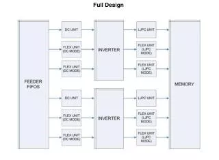
Library Block Concept • Systems in Simulink • A series of function blocks • Connected like a circuit • Used to model dynamical systems
Library Block Concept • Example system
Library Block Concept • Inputs • System A and B matrices • Roots of observer • Outputs • Preconfigured Simulink block
Design of the Observer • The full order observer equation • K0 is to be designed by the user • Eigenvalues of the characteristic error dynamics polynomial
Design of the Observer • Define the error dynamics equation
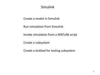
Simulink Implementation • Design Tasks • Implement the observer equation using existing Simulink blocks • Create a subsystem by grouping smaller units • Create the user interface • Validate user input • Load user matrices into observer equation • Verify correct output
Simulink Implementation • Observer user interface • Requires limited knowledge of observer design by the user
Simulink Implementation • Validation of user input • A must be square • B must have same number of rows as A • C is assumed to be of the form [1 0 0 … 0] • K must be the same length as C • The system must be completely observable
Simulink Implementation • Complete observability check • Complete controllability check
Simulink Implementation • Check for repeated roots in K vector • If root multiplicity is greater than the rank of C use ACKER() • Not terribly reliable • Breaks down for higher order systems • Otherwise use PLACE() • Much more robust • Based on algorithm designed by Kautsky and Nichols
Simulink Implementation • Block inputs • y Scalar system output • u System control command • Block outputs • Any errors are warnings for the user • Command line output of the calculated K0matrix • Vector estimate of system state
A Simple Example • Output from new block tracks system exactly after locking on
A Simple Example • Error between actual and estimate converges to zero
A More Complex Example • Output from new block tracks system exactly after locking on
A More Complex Example • Error between actual and estimate converges to zero
Summary • A Simulink full order observer library block was created • Accurate • Easy to use • Scaleable • Saves the modern control designer (or student) time • Reduces the pain and suffering inherent in the design for higher order systems
References Dorf, R.C. and Bishop, R.H.,Modern Control Systems, Tenth Edition, New Jersey:Pearson, Prentice Hall Publishing, 2004 Johnson, C.D., “Stabilization of Linear Dynamical Systems with Respect to Arbitrary Linear Subspaces,” Journal of Mathematical Analysis and Applications, Vol. 44 (1973), No. 1, pp. 175-185 Johnson, C.D., “A Unified Canonical Form For Controllable and Uncontrollable Linear Dynamical Systems,” International Journal of Control, Vol. 13 (1971), No. 3, pp. 497-517 Kalman, R.E., “Mathematical Description of Linear Dynamical Systems,” SIAM Journal of Controls, Vol. 1 (1963), pp. 152-192 Kautsky, J. and N.K. Nichols, "Robust Pole Assignment in Linear State Feedback," International Journal of Control, Vol. 41 (1985), pp. 1129-1155 Kolman, B and Hill, D.R., Linear Algebra With Applications, Seventh Edition, New Jersey:Pearson-Prentice Hall Publishing, 2001