Download
1 / 31
310 likes | 499 Vues
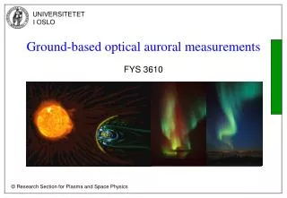
Ground-based optical auroral measurements. FYS 3610. Background. Ground-based optical measurements provides a unique way to monitor spatial and temporal variation of auroral activity at high resolution – up to 10 meters near optical zenith. All-sky camera Photometer.

E N D
Background Ground-based optical measurements provides a unique way to monitor spatial and temporal variation of auroral activity at high resolution – up to 10 meters near optical zenith. • All-sky camera • Photometer
Monochromatic filtering/ Narrow band interference filter • The half-width is about 2-3 nm
CCD light detector • Each detector element (pixel) measures the intensity in incoming light, and sends out a signal which is proportional with the light intensity. • The pixels are arranged in an array; typically 512 x 512 and up to 2000 x 2000 pixels. • More pixels = higher resolution and more data • Modern pixel sizes are between 4 and 10 µm in height and width Detector array 512 512
Charge-coupled device (CCD) • Consist of thousands of light sensitive elements arranged in an array. • Each element is an oxide semiconductor (MOS) capacitor. • The photoelectric effect produce charges on this capacitors.
Charge-coupled device (CCD) • The charges in each capacitor row is shifted to the output, and each charge is converted to a voltage. • The advantage of the CCD is that no high voltage is required (compared to the photomultiplier). • The disadvantage is low time resolution (because it is an integrating type of detector) and it is therefore not suitable to look at very weak photon sources ( without use of a light amplifier)
Charge-coupled device (CCD) • The quantum efficiency (QE) is typically 40 to 80 % for a CCD. • But, even if a photon produce one electron in the detector, this electron is not necessary detected at the detector output. Because this photon can get lost during signal transportation or be burried in noise. So QE is not a good measure of how good the detector system is.
Colours in the aurora 630.0 nm – red upper boundary Atomic Oxygen: 1D-1S transition 557.7 nm – green Atomic Oxygen : 1D - 3P transition Figure: Farge som funksjon av høyde 427.8 nm – magenta lower boundary N2+ - First neagtive band
Optics Detector array Be also aware of flipping!!
Gegraphical coverage depends on emission altitude 630.0 nm image mapped to 250 km altitude
Photometer • Measures the light intensity(for a given wavelength). • Very sensitive. • Good spatial resolution and time resolution. • A photometer cannot image the auroral morphology, so it is used as a supplement to all-sky cameras.
Photometers – Operational mode • It can be pointed at a fixed point (a given elevation). But this doesn’t give any scientific interesting data, since aurora forms typicaly has an extension of 100 – 1000 km. • Therefore it is used in a scanning mode, where the instrument sweeps out a larger area. There are two possible modes: Meridian scanning Azimuth scanning Meridian scan Azimuth scan
Photometers • A photometer (with mobility around horizontal and vertical axes) can be programmed to follow a rocket trajectory, to compare the measurements of the particle precipitation and the aurora.
Photometer • Optics • Light detector • Electronics/signal processing
Optics and filters • The optical part can be a lense or a lense system, used to focus the light on the detector(s). • A filter is used to transmitt only particular wavelengths to the detector. • Two common type of filters: Interference filter Absorbtion filter • The bandwidth of an absorption filter is much larger than for an interference filter.
Optics – angular field of view • The angular field of view decide how much of the sky the detector sees, and with that the photometers spatial resolution. • We want as large resolution as possible (small angular field of view), but at the same time as much light as possible into the detector. This is incompatible. • A common compromise is to have an angular field of view of ~ 2° (the angular field of view of the moon seen from the earth is ~ 0.5°)
Optics – angular field of view • A lense system can be used to define the angular field of view. • A singel lense and an aperture opening in front can be used to define the angular field of view.
Photon Detector • The detector is usually a photomultiplier • A Charge-Coupled Device (CCD) can also be used, and CCD based photometers are used in many satellites. • In satellites and rockets the photomultiplier tubes and the high voltage source are usually sealed in a silicone die, to prevent corona discharge and to attenuate (damp down) the vibrations.
Photomultiplier (PM) • When a photon of sufficient energy is incident on the photocatode, a single electron may be ejected (refered as a photoelectron). • The probability that a single photon produce a photoelectron that is detected in the phototube is called the quantum efficiency (QE).
Photomultiplier • QE is a function of the wavelength of the incident photon. • A typical value for quantum efficiency in a phototube is 20 - 30% ( at wavelength of 400 nm). • The photoelectron is accelerated through a potential difference, and hits a secondary electrode called a dynode. • At the this first dynode the photoelectron frees other electrons, and this secondary electrons are accelerated and focused on a second dynode and so on.
Photomultiplier • The multiplication effect take place at the dynodes, and the process results in an increasing number of available electrons (avalanche effect). • The electrons are guided by the electrostatic field between the dynodes. • An external magnetic field can distort the focusing, as the electrons travel from dynode to dynode. Therefore the photomultiplier tubes are shielded.
Photomultiplier • A photomultiplier typically have 10 – 12 stages (dynodes) and a multiplication of ~ 106 → This signal is easily detected in an external circuit. • The total voltage (the potetial difference between the photocatode and the anode) is typically 1000 – 2000 volt. • Photomultipliers are sensitive detectors of single photons, and as such are designed to operate in the dark.
Electronics /signal processing • The output signal from the photomultiplier is current pulses, where each pulse correspond to a detected photon. • This current pulses are converted to voltage pulses by a current to voltage converter. • Some of the voltage pulses generted are caused by noise, and thereby not desired. To eliminate them, a voltage discriminator is inserted. The discriminator is adjusted to remove all pulses with an amplitude smaller than a predefined limit.
Noise • There are several noise sources, but the dominating noise source fore the photomultiplier tube is thermal electron emission from the photocatode (can be reduced by cooling). • This noise result in whats known as dark current or dark counts; dark counts is the number of counts made by the photmultiplier when it is in complete darkness. • The dark current must be as low as possible, since it sets the lower limit on how low intenisty the instrument can detect.