Timing in Sequential Logic: Clocks, Inputs, and Flip-Flops
Explore the critical role of timing in sequential logic, delving into clock synchronization, asynchronous inputs, and the behavior of flip-flops and latches. Learn the concepts and constraints for correctly handling timing issues in digital systems.

Timing in Sequential Logic: Clocks, Inputs, and Flip-Flops
E N D
Presentation Transcript
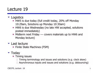
Lecture 19 • Logistics • HW5 is due today (full credit today, 20% off Monday 10:29am, Solutions up Monday 10:30am) • HW6 is due Wednesday (no late HW accepted, solutions posted immediately) • Midterm next Friday --- covers materials up to HW6 and Monday lecture) • Last lecture • Finite State Machines (FSM) • Today • Timing issues • Timing terminology and issues and solutions (e.g. clock skew) • Asynchronous inputs and issues and solutions (e.g. debouncing) 19
The “WHY” slide • Timing issues • For sequential logic, “timing” is critical because for the same inputs, the output could be different at different times (like T-flip flops). In order to achieve desired outputs, timing has to be taken into consideration. • Transistors, chips, and even wires have their own delays. Because of this, nothing could ever be perfectly synchronized. It is important to understand how fast a clock can tick based on these delays and what the common issues are in making computers to run fast and accurately. • There are synchronous and asynchronous inputs. For example, typing on the keyboard, you are putting in asynchronous inputs to the computer. Asynchronous inputs can change the outputs immediately regardless of the clock state, and it is important to know how to handle that. 19
D Q Q D Q Q CLK Latches versus flip-flops CLK D Qff Qlatch CLK behavior is the same unless input changes while the clock is high For most applications, it is not good to see Input changes instantaneously at the output 19
The master-slave D Master D latch Slave D latch Output Input D Q D Q CLK master-slave D flip-flop Because of the timing issue, it was good to use two latches as master-slave configuration or use one flip-flop. 19
D Q Q CLK Timing terminology and constraints • Setup time tsu: Amount of time the input must be stable before the clock transitions high (or low for negative-edge triggered FF) • Hold time th: Amount of time the input must be stable after the clock transitions high (or low for negative-edge triggered FF) • Clock width tw : Clock width that must be met • Propagation delays tplh and tphl: Propagation delay (high to low, low to high) (longer than hold time) tsu th th tsu D tw CLK Q tphl tplh 15 19
In Q0 Q1 Clk tsu tsu tplh tphl th th Cascading flip-flops • Flip-flop propagation delays exceed hold times • Second stage commits its input before Q0 changes IN Q1 Q0 D Q D Q > > CLK 15 19
Side note: Clock skew • Goal: Clock all flip-flops at the same time • Difficult to achieve in high-speed systems • Clock delays (wire, buffers) are comparable to logic delays • Problem is called clock skew • Avoiding clock skew: design identical delays IN Q0 Q1 CLK0 CLK1 CLK0 clocks first flipflop CLK1 clocks second flipflop CLK1 should align with CLK0, but is delayed due to clock skew Original state: IN = 0, Q0 = 1, Q1 = 1 Next state: Q0 = 0, Q1 = 0 (should be Q1 = 1) 15 19
System considerations • Use edge-triggered flip-flops wherever possible • Avoid latches • Most common: Master-slave D • Basic rules for correct timing • Clock flip-flops synchronously (all at the same time) • No flip-flop changes state more than once per clock cycle • FF propagation delay > hold time • Avoid mixing positive-edge triggered and negative-edge triggered flip-flops in the same circuit 19
CombinationalLogic CombinationalLogic Clock Asynchronous versus synchronous • Asynchronous • State changes occur when state inputs change • Feedback elements may be wires or delays • Synchronous • State changes occur synchronously • Feedback elements are clocked Asynchronous Synchronous 16 19
Asynchronous inputs • Clocked circuits are synchronous • Circuit changes state only at clock edges • Signals (voltages) settle in-between clock edges • Unclocked circuits or signals are asynchronous • No master clock • Real-world inputs (e.g. a keypress) are asynchronous • Synchronous circuits have asynchronous inputs • Reset signal, memory wait, user input, etc. • Inputs “bounce” • Inputs can change at any time • We must synchronize the input to our clock • Inputs will violate flip-flop setup/hold times 19
Debouncing • Switch inputs bounce • i. e. don’t make clean transitions • Can use RS latch for debouncing • Eliminates dynamic hazards • “Cleans-up” inputs 3.3V 0V 1 0 R Q 3.3V 1 0 S Q' 3.3V 0V 15 19
Synchronizer failure • Occurs when FF input changes near clock edge • Input is neither 1 or 0 when clock goes high • Output may be neither 0 or 1 • May stay undefined for a long time • Undefined state is called metastability D CLK Q logic 0 logic 1 19
Minimizing synchronizer failures • Failure probability can never be zero • Cascade two (or more) flip-flops • Effectively synchronizes twice • Both would have to fail for system to fail asynchronous input synchronized input D Q Q D Clk 15 19
Handling asynchronous inputs • Never fan-out asynchronous inputs • Synchronize at circuit boundary • Fan-out synchronized signal Synchronizer Async Q0 Async Q0 D Q D Q D Q Input Input Clock Clock Q1 Q1 D Q D Q Clock Clock 19
Summary: Timing issues with asynchronous inputs • For sequential logic circuits, timing issues have to be considered. • Inputs are often asynchronous and can cause problems. • Different amount of delay at different part of the circuit can cause problems also. • Solutions: • Cascade flip flops in series • Incorporate RS latch for debouncing • Design to keep timing alignment in mind (length of cable, etc) 15 19