Download
1 / 17
170 likes | 336 Vues
THERMAL CYCLE TESTS OF RF WINDOWS IN STF INPUT COUPLERS. 2010/12/07 Masato Satoh (KEK). CONTENTS. STF-1 ( Cryomodule tests with 4 cavities ) Input coupler ( structure and specifications ) Vacuum leak at low temperature S1-Global Detail of vacuum leak(sniffer & color check)

E N D
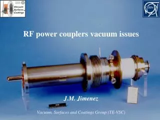
THERMAL CYCLE TESTS OF RF WINDOWS IN STF INPUT COUPLERS 2010/12/07 Masato Satoh (KEK)
CONTENTS • STF-1(Cryomodule tests with 4 cavities) • Input coupler(structure and specifications) • Vacuum leak at low temperature • S1-Global • Detail of vacuum leak(sniffer & color check) • Thermal cycle tests with sample windows • Summary
STF-0.5, STF-1(2007~2008) Cryomodule tests STF-0.5(2007) : 1 cavity STF-1(2008) : 4 cavities S1-G(now on):8 cavities
STF-1: CM test for 4 cavities Input Coupler located from 300K to 2K supplies RF power into SC-cavities. Cross-section of CM Input Coupler Warm Side 2.0K Nb-cavity Warm window(300K) Cold Side Cold window(80K)
Input coupler Warm window Warm window Cold window 5E-7 Pa(IP) 1E-6 Pa Choke: To protect brazing part from strong electric field, and to match impedance at RF window Cold Window Cold window Coaxial ceramic disk Input power in ILC Eacc = 31.5MV/m Beam current = 9mA Pin = 300 kW Cu Brazing Between ceramics and Cu
The cooling tests • STF-0.5 : cryomodule tests for 1cavity • Cooling: 2007/10/3 ~ 2007/11/22 • STF-1: cryomodule tests for 4 cavities • 1st cooling: 2008/5/21 ~ 2008/7/25 • 2K Low power test • 2nd cooling: 2008/9/9 ~ 2008/12/19 • 2K High power test No.2 coupler ・・・ 3 thermal cycles No.1, No.3, No.4 couplers ・・・ 2 ones
Vacuum leak at cold windows Warm Window Cold Window 4 warm window at 300Koccurred vacuum leak Cold window : RT~80K 3 couplers vacuum leak 1 coupler no leak 2×1 0-4 Pa m3 /s Vacuum leak was caused by thermal cycles. One potential reason might be bonded between different materials. Pin :130~270kW(20~30MV/m)
Confirmation of vacuum leak(1st : vacuum leak check) 2 cold couplers were installed in vacuum chamber Leak detector Vacuum pump
Sniffer test(sniff:嗅) Cut down choke part Sniffer probe No vacuum leak on outer brazing Sensitivity:5E-8 Pam^3/s φ6 0 deg Result of sniffer check Vacuum leak on inner brazing for all the 3 couplers 2.0E-04 Scan pitch:3mm
Results of color check (No.1,No.3) There were color reactions and cracks! No.1 Coupler No.3 Coupler 239° 65° C1 C2 R12
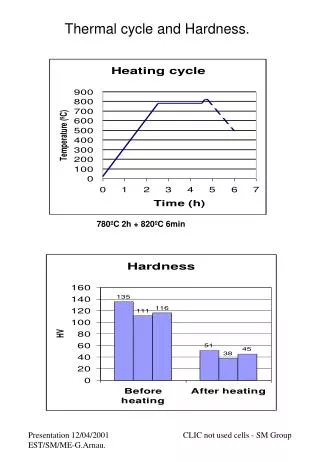
Linear Thermal Expansion Coefficient of Cu, Ceramics, Mo Actual shrinking amount : - Δ length=length×∫LTEC dT Thermal cycles NG Cool down OK 16.6×10⁻³ 2.7×10⁻³ 7.46×10⁻³ 0.65×10⁻³ 5.39×10⁻³ 0.89×10⁻³ Some measures against the thermal strain Cu pipe can absorb the thermal strain ! The original was designed by Noguchi san and Toshiba.
Mo-Ring(Toshiba) To reduce the strain of different material bonding It was developed for Tristan input couplers in 1988 300K 1200K 300K 1200K 300K Al2O3 Al2O3 Al2O3 Mo Cu Mo-ring is brazed with ceramic disk at the same time Cu Cu
Need to improve inner brazingSample windows#1,#2 2009/Sep.~ Oct. (S1-G already running) The design was changed by Noguchi & Kako Sample windows Mo-ring #2 #1 (ratio =0.8) (t1.0) Cu-Pipe Stress∝(厚度)3 Ratio3 =0.83 ~0.5 :to make stress half
300K 77Kcooling process Thickly cover Samples by Al foil(16P) Indivisually put 3 TC on Samples 4 1 5 2 6 3 8 #2 #1 #2 #1 Leak Check after Cooling Temperature Change
Results of thermal cycles Type-#1 was adopted in S1-Global Sample #1, #2 (2009 Sep ~Oct) #1: Mo,0.25t #2: Mo,0.20t Sample #3, #4 (2010 Apr ~Jun) #3 and #4 same as #1 have been exposed in 22 thermal cycles No vacuum leak
The improved ones are installed in S1-Global, and they have no trouble by now.
Summary • STF-0.5&1 cryomodule tests were carried out, -Vacuum leak happened on 3 cold windows which had Cu Pipe= 1.0t, Mo = 0.25t • Samples #1,#2 were made, and applied 6 thermal cycles - #1Cu Pipe= 0.8t , Mo =0.25t hadNo vacuum leak Type-#1 was adopted for S1-G cryomodule test #2 Cu Pipe = 0.8t , Mo =0.20t happened Vacuum leak • Sample #3, #4 same as #1 No vacuum leak against 22thermal cycle tests