Download
1 / 39
400 likes | 541 Vues
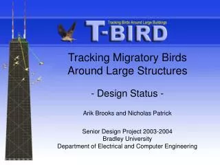
Tracking Migratory Birds Around Large Structures by Arik Brooks and Nicholas Patrick Senior Design Project 2003-2004 Bradley University Department of Electrical and Computer Engineering. Outline. Background Project summary Previous Work Detailed description System block diagram

E N D
Tracking Migratory BirdsAround Large Structures by Arik Brooks and Nicholas Patrick Senior Design Project 2003-2004Bradley UniversityDepartment of Electrical and Computer Engineering
Outline • Background • Project summary • Previous Work • Detailed description • System block diagram • Subsystems • Modes of operation • Design equations
Outline • Preliminary design work • Datasheet • Schedule • Standards/Patents • References • Equipment List
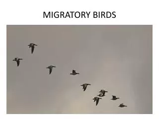
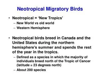
Background • Every year, many birds are killed when their migration path takes them near tall structures. • This usually occurs on overcast nights, and one widely accepted theory on why these bird kills happen is that the birds do not want to leave the lighted area near a structure and end up running into it.
Project Summary • The purpose of this project is to implement a system to track the trajectories of birds flying within the field of view of a set of cameras mounted on a rotatable boom in realtime. • The positions of the birds are determined using stereoscopic vision by placing the two cameras a known distance apart in parallel with each other.
Project Summary • The system output is a display depicting a three dimensional representation of the trajectories, and data relating to the trajectories. • Inputs to the system include the position of the boom, images detected by the cameras, calibration information, and confidence level threshold.
Previous Work • Seniors Brian Crombie and Matt Zivney worked on a senior project in Spring 2003 with the goal of tracking birds around tall structures via stereoscopic imaging. • They achieved basic object tracking in a laboratory environment with major limitations. • The groundwork laid out in their project (algorithms, design equations, software organization, etc.) will be used as a starting point for our system.
System Block Diagram System
Subsystems • Cameras • Boom • Frame Grabber • PC • Display and Interface
Camera Subsystem • The camera subsystem includes two cameras mounted in parallel a known distance apart allowing objects to be located in space. • Inputs • Photons -- Images from the environment within the field of view of the cameras • Synchronization signal -- Signal from an external source (frame grabber) to coordinate the capturing of images • Outputs • Data -- Image data transmitted to the frame grabber • Operation in Modes • The cameras capture images continuously
Boom Subsystem • The boom subsystem holds the cameras in parallel and rotates via a stepper motor. • The position of the boom is determined from the output of an encoder. • Inputs • Stepper Motor Control Signal -- Rotates the boom in two directions • Outputs • Encoder Output -- Signal to the PC to determine the current angle of the boom • Operation in Modes • The boom operates (changes position) only in Setup mode
Frame Grabber Subsystem • The frame grabber simultaneously captures images from both cameras and supplies the data to the PC. • Inputs • Data -- Image data from the cameras • Setup -- Information from the PC • Outputs • Image Data to PC • Synchronization Signal -- Signal to the cameras to coordinate the capture of images • Operation in Modes • The frame grabber operates continuously along with the cameras
PC Subsystem • Inputs • Image Data -- Arrays of intensity information from the frame grabber representing the collected images • Encoder -- Angle information from the boom encoder • Desired Boom Position -- Input from the user for desired boom position • Real-time/Delay -- Input from user determining whether or not to calculate and display the trajectory information in real-time • Calibration Input -- Calibration data for the cameras being used • Confidence Level -- User defined level of non-linearity in trajectories allowable for consideration
PC Subsystem • Outputs • Display -- Trajectories displayed in a three dimensional representation and graphical user interface • Statistics -- Pertinent information about the objects locations and trajectories (e.g. Number of birds within x distance of the cameras, maximum velocity, etc.) • Raw Data -- Data file containing all position data for later analysis • Operation in Modes • The PC is continuously operating in every mode
Display and Interface Subsystem • The trajectories will be displayed on a standard computer monitor. • The user will interface with the system using a standard computer keyboard and mouse. • Inputs • Display Information • User Inputs • Outputs • Image Display • User Data • Operation in Modes • The Display and Interface will be used in Setup and Display modes
Modes of Operation • Setup • Monitoring • Data Acquisition • Display and Computation
Preliminary Design Work • Based on preliminary work performed in the laboratory, it was determined that a better method of transient object correlation needs to be implemented to achieve the tracking of a large number of objects at one time. • When objects cross paths or get close to each other, the current transient correlation algorithm fails to differentiate between those objects accurately and errors occur.
Preliminary Design Work • The basic flow of the software to be designed including better organization and correlation method was determined. • Preprocessing • Read in image, record initial time stamp and time between frame grabs • Discard areas that are not within field of view of both cameras • Perform a background subtraction to extract moving objects • Threshold and convert each image to B/W • Apply filters • Find areas/centroids of all objects
Preliminary Design Work • Correlation/Trajectory • Input areas/centroids found in preprocessing • Save data for later use • Find every “possible” 3d position for the objects in the present frame • to be “possible”, must be within 30 pixels of each other between cameras in horizontal position • continued...
Preliminary Design Work • Correlation/Trajectory (continued) • Search for closest position to predicted position, within the user defined threshold, for each object based on its previous two locations • Search for objects that were first detected in the previous frame based on closest position and area within a threshold (Different from the user defined threshold) • Correlate any remaining objects between two cameras based on closest horizontal distance and area • Calculate new predicted positions for any object with two or more data points in time • Display
Datasheet • Average Migratory Bird Size (AMBS): TBD • Max # of Objects Tracked Simultaneously: TBD • Max Distance from Cameras: TBD • Min Distance from Cameras: TBD • Max Location Error: TBD • Light Level Sensitivity: • Lab Cameras: 0.22 Lux • Low Light Cameras: 0.0002 Lux • Max Framerate: TBD • System Latency: TBD • Max Trackable Bird Speed: TBD • Total Volume of Space Observed: TBD • Boom Rotation Step Resolution: TBD
Test Plan • There will be four primary test procedures that will be performed to verify the system specifications: • Location Accuracy • track an AMBS object in known trajectories (including trajectories proceeding primarily towards and away from the cameras) and compare the measured and actual locations • Max/Min Distance from Cameras • track an AMBS object in known trajectories and check accuracy/ability to track • Max # Objects • TBD • Contrast Resolution • track objects of various known intensities in front of a variety of backgrounds
Standards • There are no overarching standards that apply to bird tracking, but several standards are used to interface cameras to the PC. • NTSC • The cameras selected produce NTSC compatible signals, which is the standard in North America • The Frame Grabber converts NTSC inputs to digital images • DirectX • DirectX is a defacto standard for Microsoft Windows which includes a programming interface to video capture devices such as frame grabbers • DirectX was chosen over proprietary APIs to maintain a maximum amount of hardware independence
Patents • Patent #6,366,691 • Stereoscopic image processing apparatus and method • Patent #6,028,954 • Method and apparatus for three-dimensional position measurement • Patent #6,035,067 • Apparatus for tracking objects in video sequences and methods therefor • Patent #5,812,269 • Triangulation-based 3-D imaging and processing method and system
References http://www.intel.com/research/mrl/research/openCV/ Pinhole camera model, image processing reference. http://www.digibird.com/primerdir/eqn.gif Equations relating focal length to zoom http://www.ipsimaging.com/support/camerasensitivity.htm Light levels for various time of day and weather conditions. http://sportscience.org/adi2001/adi/services/support/faq/software_genlock.asp Estimating position when synchronized cameras are not available. http://www.fmsystems-inc.com/vtmtips_article.htm Using line lock cameras. http://www.imaginghardware.com/Tutorials/Docs/t00002A.asp Equation relating focal length to target object size, distance, and CCD width. http://www.machinevisiononline.org/public/articles/cohu.PDF Measurements for various CCD sizes. http://cegt201.bradley.edu/projects/proj2003/birdtrak/pdf/proj_prop.pdf Project proposal from previous group Chen, Tieh-Yuh; Bovik, Alan Conrad; Cormack, Lawrence K. “Stereoscopic Ranging by Matching Image Modulations,” IEEE Transactions on Image Processing. Vol 8, # 6, June 1999, pg 785-797.
Equipment List • Cameras and Lenses • Lab • Sanyo VCB-3444 • Rainbow L8DC4P Auto Iris Lens • Low Light • Hitachi KP-200E • $920 at www.opsci.com • DV10x7.5A-SA2 Auto Iris Lens • $273 at www.opsci.com
Equipment List • Video Capture Card • Data Translation DT3132 Dual Frame Grabber • Supports simultaneous acquisition of images from two sources. • Programmable through DirectX
Equipment List • PC • Windows 2000 or higher OS • DirectX 8.1 or higher installed • One PCI slot for frame grabber • Enough processor power for real-time operation • Development software • DirectX 8.1 SDK • Microsoft Visual Studio 6.0 • MATLAB 6.5 with image processing toolbox