Download
1 / 19
190 likes | 241 Vues
Explore the components of Codan 5700 Series C-Band Transceiver, including SSPA types, LNA, TRF, and power supply units. Learn about block diagrams, temperature compensation, synthesizers, and connections. Enhance your understanding of C-Band Converter Modules and operational guidelines.

E N D
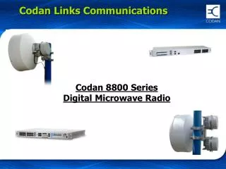
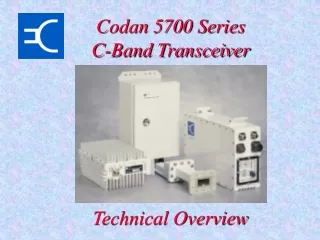
Codan 5700 SeriesC-Band Transceiver Technical Overview
5700 Series C-Band Transceiver Components • type 5700 Converter Module • SSPA types • 5705 - 5W • 5710 - 10W • 5720 - 20W • 5730 - 30W • 5740 - 40W • 5760 - 60W • 5712H - 120W • LNA & TRF • type 5582 Power Supply Units
Tx RF (6GHz) Transmit IF Input (70/140MHz) SSPA Up/Down Converter SSPA Pwr & Control Monitor & Control OMT Receive IF Output (70/140MHz) LNA TRF Antenna Rx RF (4GHz)+ LNA Pwr 48V DC Power Power Supply AC Mains C-Band Transceiver Block Diagram
48V DC Power AC Mains Tx RF (6GHz) Transmit IF Input (70/140MHz) SSPA Up/Down Converter SSPA Control Monitor & Control OMT Receive IF Output (70/140MHz) LNA TRF Antenna Rx RF (4GHz)+ LNA Pwr HPA Transceiver Block Diagram
C-Band Converter Module Not on CE converters
C-Band Converter Module Transmit Side Receive Side
IF Paths • Tx IF input attenuator • 25dB typical range, 1 dB steps. • 10dB gain from Tx IF input to Tx RF output of converter at attenuator setting of 0dB. • Rx IF output attenuator • 25dB typical range, 1 dB steps. • 45dB gain from Rx RF input to Rx IF output of converter at attenuator setting of 0dB. • Tx IF switch - controlled by: • Warm-up timer
Tx IF PathCable CompensationNo longer available with CE market converters • Cable Compensation • Provides up to 1.2dB boost (70 MHz) or 2.5dB boost (140MHz) in 16 steps • Suits over 120m (400ft) of low loss Belden 9913 coax • Ideal for DAMA systems - constant EIRP across entire IF band
Tx IF PathTemperature Compensation • Temperature Compensation • Compensates for gain variations of SSPA and Converter • Selectable for 5W, 10W or higher SSPA’s (via SPT5, 6 or 7) • ±1.0dB level stability over -40oC to +55oC • Look-up tables in EPROM • Uses temperature sensors in SSPA and Converter
Synthesisers • All oscillators locked to 10MHz oven controlled reference • 10MHz Reference Warm-up timer • 5-14 minute warm-up from cold switch-on (14 mins. at -40C !) • 30 second warm-up if power interrupted momentarily • Timer Over-ride • RS232 (SRO1) • Allows transmission immediately from switch-on • Warm-Up LED flashes • Beware frequency accuracy! • SHF oscillator signals: Up and Down paths • Fixed 2225 MHz offset for single synthesiser models only • Step size 1MHz in both single & dual synthesiser models
LNA Connections • LNA power source is DIP switch Selectable (LNA+15V) • LNA Power via Rx RF input • LNA alarm and voltage shut down if >250mA • LNA alarm if <50mA or short circuited • Take care when testing at this input (turn off DC or use DC block) • LNA Power via separate connector • Current limited (max 400 mA) • LNA alarm relay contact input
SSPA Connections • Low Power SSPA Interface • 48V DC - via fuse in Converter • SSPA temperature sensor for gain compensation • SSPA Fail • SSPA over temperature alarm • Fan Supply (+12V) • High Power SSPA Interface • 110/220V AC Mains Input • SSPA Fail • 48V DC to Converter • SSPA over temperature alarm • Fan Supply • Converter monitors current from fan to detect fan fault • Fault monitoring can be disabled (SFE0) for SSPA’s without a fan • Not available with high power SSPAs (self-monitoring by SSPA)
RF INPUT FROM CONVERTER 6V5 OUTPUT BIAS -3V2 INPUT BIAS NEGATIVE RAIL GENERATOR 5V1 FAULT DETECTION UNDER VOLTAGE OVER 10V3 TEMP. DC IN 10V SWITCHED TEMP. SSPA ACTIVATE 6V5 SWITCHED SENSOR SUPPLY FAULT -3V2 SWITCHED MODE FROM CONVERTER TEMP. FAULT OVERCURRENT SUPPLY AND LOGIC TEMP. SENSOR UNDERVOLTAGE OVER TEMP. TEMP. SENSOR FAN SSPA Block Diagram
Low Power SSPA (1) • N-connector or Waveguide output options • Internal input isolator for good input VSWR • Internal output isolator for protection and good O/P VSWR • High system gain: 74dB (10W to 40W SSPA’s) nominal • Operates from 48V DC (fully floating) • All bias supplies are generated internally • Fan supply provided separately by Converter Module • Internal fault monitoring of GaAs FET bias conditions • Automatic shut-down if: • Bias fault detected when SSPA on - needs to be manually reset • SSPA case temperature is >75oC, automatically resets when SSPA cools down
Low Power SSPA (2) • Two temperature sensors: • Over Temperature shut-down • Gain v Temperature compensation (in Converter)High MTBF fan standard on10W, 20W, 30W and 40W SSPA’s • 5W SSPA’s are convection cooled - no fan • Maintenance • Check heatsink fins for obstructions (webs, nests, insects etc.) • Clean heatsink to remove dust, dirt, grime etc. • Recommendation - check at least once per year
High Power SSPA • Available in 60W and 120W • Completely sealed assembly • WR137 waveguide output • Internal Temperature compensation • Full monitor & control from 5700Up/Down Converter • DC power supplied to the Up/DownConverter from SSPA • SSPA’s can also be operated in a stand alone configuration via front panel controls or serial commands
5582 Mains Power Supply • Switch Selectable operation from 115V AC or 230V AC -15%/+20% • Transceiver uses wide input range DC-DCconverters • Provide low power consumption • High efficiency over full 37V to 76V range • Simple design ensures high reliability. • toroidal power transformer and bridgerectifier combination
Transceiver Controls • Power • Off - All circuits off • Stand-by - Only reference oscillator and microprocessor on • On - Operational mode • SSPA • Inhibit • SSPA cannot be turned on remotely (Serial or Control Input) • Remote • SSPA on only if turned on remotely (Serial or Control Input) • Activate • SSPA on unless inhibited remotely (Serial or Control Input) • DIP Switches
Front Panel Indicators • Power • Stand-by - Only reference oscillator and microprocessor on • On - Operational mode • Warm-Up - In warm-up mode, flashes if Timer Override selected • SSPA • SSPA On - SSPA on! • Fault • Conv • One or more phase locked loops in the Converter are unlocked • LNA • LNA fault detected (current sense at Rx RF input or fault input) • SSPA • SSPA fault (only detected when SSPA is activated) • Temp • SSPA case temperature too high • Fan • Fan not operating or too slow (low power transceivers only)