Understanding Circuit Basics and Components in Modern Electronics
This comprehensive guide covers the fundamentals of electronics through three parts, including circuit basics, resistor analysis, and voltage dividers. It provides hands-on lab experiences utilizing essential equipment such as DC sources, function generators, digital multimeters, and oscilloscopes. The course is designed to equip participants with the necessary skills to communicate effectively with electrical engineers, prepare for the electronics sections of the FE exam, and apply engineering problem-solving skills in real-world scenarios, particularly in the context of modern automobile electronics.


Understanding Circuit Basics and Components in Modern Electronics
E N D
Presentation Transcript
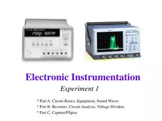
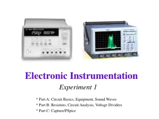
Experiment 1 * Part A: Circuit Basics, Equipment, Sound Waves * Part B: Resistors, Circuit Analysis, Voltage Dividers * Part C: Capture/PSpice
Motivation • Modern Systems • mechanical component • electrical component • (computer component) • You will be able to communicate with EE’s • You will be able to take the electronics sections of the FE exam • You will be using Engineering problem solving skills.
Automobile Electronics • Previously all mechanical systems have become increasingly electronic • Over the past few years, for example, the automobile has begun to use more computers (microcontrollers) • How many microcontrollers are typically found in a modern automobile?
Part A • Circuit Basics • Equipment • Sound Waves
Physical Model for a DC circuit pump = voltage source water = flow of current ocean = ground pipe = wire
Physical Model for Resistance pebbles in pipe = resistance to flow of current
Alternating Current Generators http://micro.magnet.fsu.edu/electromag/java/generator/ac.html
AC Circuits Note symbol for AC voltage source
More on Phase Shift Negative phase shift: “Lag in phase, lead in time” Positive phase shift: “Lead in phase, lag in time”
ADJUST VOLTAGE LEVEL Do Not Use TOGGLE OUTPUT ON/OFF -25 to 0 VOLTS 0 to 6 VOLTS GROUND GROUND 0 to 25 VOLTS DC Source E3631A –Only for section 2 Note: The connection that looks like the ground symbol is the ground for the building, not the return path for the circuit.
Function Generator 33120A – Only available in JEC 4107 Note: The SYNC connection will give you a signal, but it will not be the one you have set the function generator to display. Do not accidentally plug into it.
Digital Multimeter 34401A – We will have some hand held meters in section 1 for resistance measurements Note: Always use the voltage plugs on the right as indicated.
Digital Multimeter The IOBoard can read voltages but it isn’t an Ohmmeter, We will use hand held meters for resistance measurements
Oscilloscope 54600B – you guessed it – JEC 4107 Note: Black lead of scope channel is ALWAYS ground
Protoboards Note: Banana connectors are not connected internally to the holes in the board.Check continuity of power rails at top and bottom.
Reading Resistors Bands: XYZT Resistance = http://www.dannyg.com/javascript/res/resload.htm
How Ears Work Pitch = frequency Amplitude = loudnessSome pitches sound louder to your ears. http://members.aol.com/tonyjeffs/text/dia.htm
Part A – Do the lab now • Use your kit if you purchased one, purchase one if you haven’t • Some of Part A can be done without the kit, just with the IOBoard • If you don’t have a kit • Make sure that you have the software loaded and that the IOBoard is working • We have some spare protoboards and speakers • There will be time during the next 2 classes to catch up • Next class we start Part B of Experiment 1 • Any questions?
Part B • Resistors • Voltage Dividers • Impedance • Capacitors and Inductors • Equipment Impedances • Circuit Analysis • Agilent Intuilink Software
Measuring Voltage Total Voltage: Voltage across resistors: Voltage at points wrt GND:
Voltage Dividers The voltage is divided up in a manner that is proportional to the resistances of the resistors in a series circuit.
More on Voltage Dividers Always add up resistors relative to ground to get the voltage at a point. You can use a voltage divider on a series portion of a circuit. You cannot use a voltage divider on a non-series circuit.
Impedance vs. Resistance • Resistance is a property of a material that causes a reduction in the rate of flow of electrons. • Impedance is the reduction in the rate of flow of electrons caused by the material (resistance) AND other the properties of the component involved (reactance). • Resistors have no reactance. So the impedance of a resistor is equal to its resistance only. • Reactance varies with the frequency of the input. Resistance remains the same at all frequencies. • Both impedance and resistance are measured in ohms.
Impedance • Definition: A general measure of how a component or group of components pushes against the current flowing through it. • Impedance = resistance + reactance • Impedance is used to refer to the behavior of circuits with resistors, capacitors and other components. • When we consider components in a theoretical circuit diagram, the impedance of inductors and capacitors is their reactance only. Any resistance is modeled separately as a resistor. So theoretical capacitors and inductors have impedance, but no resistance.
Capacitors Capacitors consist of two plates with a dielectric material in-between. When a potential difference is placed across the plates, a charge builds up until it is large enough to cause a discharge across the plates through the material.
Reading Capacitors - towards ground Larger capacitors have the number of microfarads written on them directly. Smaller capacitors use a code based on the number of picofarads. We generally use microfarads, so… XYZ = XY * 10Z * 10-6mF
Capacitor Impedance Note: Real capacitors have effectively no resistance, so impedance is reactance for all capacitors.
Inductors • An inductor is a coil of wire through which a current is passed. The current can be either AC or DC.
Inductors • This generates a magnetic field, which induces a voltage proportional to the rate of change of the current.
Combining Inductors • Inductances add like resistances • Series • Parallel
Inductor Impedance Note: Real inductors always have a small resistance (that is not shown in these circuits). The impedance of the theoretical inductor shown is only its reactance.
Equipment Impedances • Each measuring device changes the circuit when you use it. • The impedance of the device helps you understand how much. • Device Impedances • Function Generator: 50 ohms • ‘Scope: 1Meg ohms • DMM (DC voltage): 10Meg ohms • DMM (AC voltage): 1Meg ohms • DMM (DC current): 5 ohms (negligible)