
2.2 Network Devices
E N D
Presentation Transcript
2.2 Network Devices Connectors, Repeaters, Hubs, Bridges, Switches, Routers, NIC’s
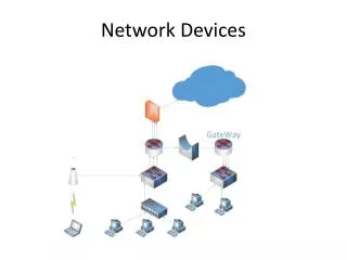
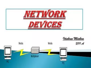
Network Devices • Network is interconnection of devices. • For these connection we need to use the connecting devices. • Also called as Network Control Devices.
The purpose • Allow a greater number of nodes to be connected to the network. • Extend the distance over which a network can extend. • Localize traffic on the network. • Can merge existing networks. • Isolate network problems so that they can be diagnosed more easily.
Connectors • To connect cable between two computers. • Connectors are of different type such as – • Twisted Pair cable • Co-axial Cable • Fibre optic cable. • Connectors are type such as- • Jacks • Plugs • Sockets and ports
Connectors Example: • RS232 and V35 for serial interface • RJ45 and BNC connectors for Ethernet. • SC or ST connectors for fibre optic
Repeaters • Signal attenuation or signal loss – signal degrades over distance • Repeaters clean, amplify, and resendsignals that are weakened by long cable length. • Built-in to hubs or switches • A repeater operates only at the PHYSICAL layer. • It connects two segments of the same network. • Single port, multi-port repeaters.
Repeaters Function of a repeater
HUB • A hub is used as a central device. • Connects the computers in star topology. • Hubsare simple devices that direct data packets to all devices connected to the hub. • Hubs regenerate and retime network signals • hubs work at the OSI physical layer • They cannot filter network traffic. • They cannot determine best path • They are really multi-port repeaters
Types of Hub • Passivehub • is just a connector - connects the wires coming from different branches. • The signal pass through a passive hub without regeneration or amplification. (distance 300 feet) • Active hubs or Multiport repeaters- • They regenerate or amplifythe signal before they are retransmitted (distance -2000 feet). • Intelligent Hub • Regenerate the signals and perform network management and intelligent path selection.
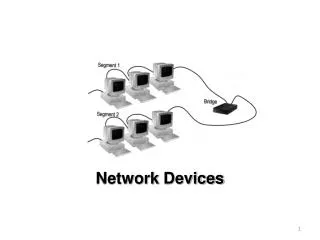
Bridges • Operates in both the PHYSICAL and the data link layer. • As a PHYSICAL layer device, it regenerates the signal it receives. • As a data link layer device, the bridge can check the PHYSICAL/MAC addresses (source and destination) contained in the frame.
Bridges • A bridge has a table used in filtering decisions. • It can check the destination address of a frame and decide if the frame should be forwarded or dropped. • For frame to be forwarding, it specify the port. • Limit or filter traffic - keeps local traffic local yet allow connectivity to other parts (segments).
Characteristics of Bridges • Routing Tables– Contains one entry per station of network.– Is used to determine the network of destination. • Filtering– Packets are filtered with respect to their destination and multicast addresses. • Forwarding– the process of passing a packet from one network to another. • Learning Algorithm– the process by which the bridge learns how to reach stations on the internetwork.
Types of Bridges • Transparent Bridge • Also called learning bridges • Build a table of MAC addresses as frames arrive. • Ethernet networks use transparent bridge • Duties are : Filtering frames, forwarding and blocking • Source Routing Bridge • Used in Token Ring networks • Frame contains not only the source and destination address but also the bridge addresses.
Advantages And Disadvantages • Advantages of using a bridge– Extend physical network– Reduce network traffic with minor segmentation– Reduce collisions– Connect different architecture • Disadvantages of using bridges– Slower than repeaters due to filtering– Do not filter broadcasts– More expensive than repeaters
Switched networks • Shared ethernet networks perform best when kept to 30-40 percent full capacity • This is a result of CSMA/CD • A LAN switch is a high-speed multiport bridge which segments each port into its own collision domain and can access the full bandwidth
Switches • Each port is a simulated segment to itself
Store and Forward Switches • Do error checking on each frame after the entire frame has arrived into the switch • If the error checking algorithm determines there is no error, the switch looks in its MAC address table for the port to which to forward the destination device • Highly reliable because doesn’t forward bad frames • Slower than other types of switches because it holds on to each frame until it is completely received to check for errors before forwarding
Cut Through Switch • Faster than store and forward because doesn’t perform error checking on frames • Reads address information for each frame as the frames enter the switch • After looking up the port of the destination device, frame is forwarded • Forwards bad frames • Performance penalty because bad frames can’t be used and replacement frames must be sent which creates additional traffic
Fragment free cut through switch • Combines speed of cut through switch with error checking functionality • Forwards all frames initially, but determines that if a particular port is receiving too many bad frames, it reconfigures the port to store and forward mode • Preferred switching solution
Unmanaged/Intelligent switches • Unmanaged – provides LAN’s with all the benefits of switching • Fine in small networks • Intelligent switches tracks and reports LAN performance statistics • Have a database ASIC (application specific integrated circuit) on board to collect and store data which you view through a software interface
Layer 3 switch • By definition a switch filters or forwards frames based on MAC addresses. This makes a switch a layer 2 device. • Now we have layer 3 switches which have routing capability. If a data frame can’t be switched it is routed. • Each port is a separate LAN port, but the forwarding engine actually calculates and stores routes based on IP addresses, not MAC addresses • Usually support only IP or IP and IPX
VLAN Switches • Virtual local area network • Each port on a switch defines a collision domain • The entire switch forms a single broadcast domain • VLANs can define multiple broadcast domains • Network traffic that is directed to all computers on the network can be segmented to transmit only on a specific VLAN. • Improves bandwidth on a the VLAN’s because each VLAN filters the network-to-network broadcast traffic as well as the collision traffic from other VLAN’s
Physical Layer Broadcast • Physical layer broadcasts – implemented by non-switched Ethernet networks through shared cabling and hubs • Each bit that is transmitted is physically received by every station • Switches and VLAN’s don’t do physical layer broadcasts
MAC-level broadcast • MAC-level broadcast – deal with how to handle MAC level broadcast frames; that is the data frames that have a broadcast destination MAC address • MAC-level broadcast frames are addressed to all MAC addresses on a given network (not a network segment, but an actual network as defined by its network address) • A regular switch forwards all broadcast frames out all ports, but a VLAN switch forwards broadcast frames only to ports that are part of the same VLAN • Multiple switches can be part of the same VLAN
VLAN Switches • None of the VLAN’s can communicate unless each VLAN is connected to a router or layer 3 switch • Each VLAN is separating collision traffic associated with MAC Addresses (layer 2) and each VLAN is separating the network-to-network broadcast traffic. In other words each VLAN is acting as a separate network so a layer 3 device is necessary for them to communicate