Tools for Discovery
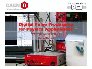
Tools for Discovery. Digital Pulse Processing for Physics Applications PSI - March 15th 2011 Carlo Tintori. Outline. Description of the hardware of the waveform digitizers Overview on the CAEN Digitizer family Use of the digitizers for physics applications

Tools for Discovery
E N D
Presentation Transcript
Tools for Discovery Digital Pulse Processing for Physics Applications PSI - March 15th 2011 Carlo Tintori
Outline • Description of the hardware of the waveform digitizers • Overview on the CAEN Digitizer family • Use of the digitizers for physics applications • Comparison between the traditional analog acquisition chains and the new fully digital approach • DPP algorithms: • Pulse triggering • Zero suppression • Pulse Height Analysis • Charge Integration • Gamma-Neutron discrimination • Time measurement Reproduction, transfer, distribution of part or all of the contents in this document in any form without prior written permission of CAEN S.p.A. is prohibited
Digitizers vs Oscilloscopes • The principle of operation of a waveform digitizer is the same as the digital oscilloscope: when the trigger occurs, a certain number of samples is saved into one memory buffer (acquisition window) • However, there are important differences: • no dead-time between triggers (Multi Event Memory) • multi-board synchronization for system scalability • high bandwidth data readout links • on-line data processing (FPGA or DSP) Reproduction, transfer, distribution of part or all of the contents in this document in any form without prior written permission of CAEN S.p.A. is prohibited
Highlights • VME, NIM, PCI Express and Desktop • VME64X, Optical Link (CONET), USB 2.0, PCI Express Interfaces available • Memory buffer: up to 10MB/ch (max. 1024 events) • Multi-board synchronization and trigger distribution • Programmable PLL for clock synthesis • Programmable digital I/Os • Analog output with majority or linear sum • FPGA firmware for Digital Pulse Processing • Software for Windows and Linux • From 2 to 64 channels • Up to 5 GS/s sampling rate - Up to 14 bit • FPGA firmware for Digital Pulse Processing Reproduction, transfer, distribution of part or all of the contents in this document in any form without prior written permission of CAEN S.p.A. is prohibited
Digitizers Table Reproduction, transfer, distribution of part or all of the contents in this document in any form without prior written permission of CAEN S.p.A. is prohibited
Architecture Reproduction, transfer, distribution of part or all of the contents in this document in any form without prior written permission of CAEN S.p.A. is prohibited
Digitizers for Physics Applications • Traditionally, the acquisition chains for radiation detectors are made out of mainly analog circuits; the A to D conversion is performed at the very end of the chain • Nowadays, the availability of very fast and high precision flash ADCs permits to design acquisition systems in which the A to D conversion occurs as close as possible to the detector • The data throughput is extremely high: it is no possible to transfer row data to the computers and make the analysis off-line! • On-line digital data processing in needed to extract only the information of interest (Zero Suppression & Digital Pulse Processing) • The aim of the DPP for Physics Applications is to provide FPGA algorithms able to make in digital the same functions of analog modules such as Shaping Amplifiers, Discriminators, Charge ADCs, Peak Sensing ADCs, TDCs, Scalers, Coincidence Units, etc. Reproduction, transfer, distribution of part or all of the contents in this document in any form without prior written permission of CAEN S.p.A. is prohibited
Traditional chain: example 1charge sensitive preamplifiers • Typically used with semiconductor detectors (Si, Ge) • The preamp. output signal is rather slow (typ. decay time = 50us) • Very high energy resolution (good S/N ratio) Reproduction, transfer, distribution of part or all of the contents in this document in any form without prior written permission of CAEN S.p.A. is prohibited
Traditional chain: example 2trans-impedance (current sensitive) preamplifier • Typ. used with scintillators + PMTs or SiPMs • The preamplifier is optional (the gain is already in the PMT) • Fast signals (typ. 10-100ns) Reproduction, transfer, distribution of part or all of the contents in this document in any form without prior written permission of CAEN S.p.A. is prohibited
Benefits of the digital approach • One single board can do the job of several analog modules • Full information preserved: A/D conversion as early as possible, data reduction as late as possible • Reduction in size, cabling, power consumption and cost per channel • High reliability and reproducibility • Flexibility (different digital algorithms can be designed and loaded at any time into the same hardware) Reproduction, transfer, distribution of part or all of the contents in this document in any form without prior written permission of CAEN S.p.A. is prohibited
Standard vs DPP firmware Standard Firmware: • raw waveform mode (event = sequence of samples) • common trigger on all channels simultaneously • trigger time stamp • channels self trigger: digital discriminator with absolute threshold • channel self triggers ORed to make the common trigger • zero suppression (sole data reduction technique) DPP Firmware • on-line dead-timeless data processing • multi-parametric list mode (event = time stamp, pulse height, charge, etc…) • combined acquisition mode: list + short waveform for further analysis off-line • channels can trigger independently • pulse triggering: baseline restore, smooth filters, rise time discriminator, etc… • pulse time stamp • pulse shape analysis (e.g. gamma neutron discrimination) • individual trigger propagation on channel basis, also from board to board Reproduction, transfer, distribution of part or all of the contents in this document in any form without prior written permission of CAEN S.p.A. is prohibited
Raw waveform mode vs DPP events STD FW Typ. Nsample > 1K DPP FW Typ. Nsample < 100 Reproduction, transfer, distribution of part or all of the contents in this document in any form without prior written permission of CAEN S.p.A. is prohibited
Coincidence and Event correlation • When running in list mode, the bandwidth requirement is much lower than in raw waveform mode. Example: time stamp + energy = 8 bytes; 8 channels @ 1Mcps = 64 MB/s; fits the CONET bandwidth. • General Rule: read all events as long as you have enough bandwidth (i.e. make data suppression as late as you can) • Coincidence and anticoincidence applied off-line using the time stamps • When hardware coincidence is needed, you can: • Use internal coincidence between the channels of a board to make a common trigger (STD FW only) • Use analog sum or majority on the DAC output (only for VME board with STD FW) • Use on-line coincidence in the x720+DPP-CI (only between couples of channels) • Use GPIOs on the front panel to propagate trigger inputs/outputs from/to external logic (e.g. V1495) Reproduction, transfer, distribution of part or all of the contents in this document in any form without prior written permission of CAEN S.p.A. is prohibited
Trigger and timing filter (I) • Pulse triggering is the basis for all DPP and Zero Suppression algorithms • Fast Shaping filter: digital version of the RC-CRN filter (N=1, 2) • Immune to baseline fluctuation and low frequency noise (ground loop) • Pulse identification also with the presence of pile-up • High frequency noise rejection (RC smoothing filter) • Can operate as a digital CFD • Zero crossing for precise timing information • Off-line interpolation to overcome the sampling period granularity • Zero crossing of CFD can also be used for rise time discrimination Reproduction, transfer, distribution of part or all of the contents in this document in any form without prior written permission of CAEN S.p.A. is prohibited
Trigger and timing filter (II) Reproduction, transfer, distribution of part or all of the contents in this document in any form without prior written permission of CAEN S.p.A. is prohibited
Zero Suppression • Data reduction algorithms can be developed to reduce the data throughput: • Full event suppression: one event (acquisition window) is discarded if no pulse is detected inside the window • Zero Length Encoding: only the parts exceeding the threshold (plus a certain number of samples before and after) are saved. • The zero suppression is available also with the standard FW (no DPP) ZLE Reproduction, transfer, distribution of part or all of the contents in this document in any form without prior written permission of CAEN S.p.A. is prohibited
DPP-TF DPP-TF PULSE HEIGHT ANALYSIS Reproduction, transfer, distribution of part or all of the contents in this document in any form without prior written permission of CAEN S.p.A. is prohibited
DPP-TF topics • Digital implementation of the shaping amplifier + peak sensing ADC (Multi-Channel Analyzer) • Charge sensitive preamplifier directly connected to the digitizer • Implemented in the 14 bit, 100MSps digitizers (mod. 724) • Use of trapezoidal filters to shape the long tail exponential pulses • Pile-up rejection, Baseline restoration, ballistic deficit correction • Low dead time => high counting rate • Energy and timing information can be combined • Best suited for high resolution spectroscopy (HPGe and Si detectors) • Also suitable for homeland security and biomedical applications Reproduction, transfer, distribution of part or all of the contents in this document in any form without prior written permission of CAEN S.p.A. is prohibited
DPP-TF Block Diagram Reproduction, transfer, distribution of part or all of the contents in this document in any form without prior written permission of CAEN S.p.A. is prohibited
Example of trapezoidal filter output Trapezoid Height = Energy Pile-up Reproduction, transfer, distribution of part or all of the contents in this document in any form without prior written permission of CAEN S.p.A. is prohibited
DPP-TF vs Analog Chain set-ups N1470High Voltage N968 Shaping Amplifier N957 Peak Sensing ADC Energy C.S. PRE Ge / Si DT5724 14bit @ 100MSps Digitizer + DPP-TF Energy Time Reproduction, transfer, distribution of part or all of the contents in this document in any form without prior written permission of CAEN S.p.A. is prohibited
Dead Time in the DPP-TF • Unlike the analog chain, in the DPP-TF there is no conversion time • The A/D conversion and the pulse processing is always alive; dead time in the energy filter is only given by the trapezoid overlap (Trise + Tflat) • Although pile-up causes the loss of energy values, the timestamps is given for almost all pulses: true rate can be calculated • Double pulse resolution Rise Time (two pulses separated by at least the rise time can be distinguished) • The rise time discriminator allows double pulses piling up on the rising edge to be detected and counted twice • Residual multiple pulses that cannot be distinguished (despite the RTD) can be taken into account on a statistical basis • Histogram (spectrum) calculated off-line: easy implementation of techniques for the ‘dead-time’ correction (loss of energy counts) • The number and the timing of lost counts is known: they can be dynamically re-distributed on the histogram. This is very important in the cases where the activity is not constant in time. Reproduction, transfer, distribution of part or all of the contents in this document in any form without prior written permission of CAEN S.p.A. is prohibited
Individual inter-channel triggering • Feature developed for the project Prospectus (compton camera) • Mainly needed in segmented or clove detectors • One channel triggers itself and also neighbour channels (also from board to board • Individual TRG-IN and TRG-OUT lines from each channel to the Front Panel GPIO connector (8 inputs + 8 outputs) • External trigger unit (V1495) for the coincidence matrix implementation • Available in the new DPP-TF (x724 series) • Can be implemented in the x720 and x751 series as well Reproduction, transfer, distribution of part or all of the contents in this document in any form without prior written permission of CAEN S.p.A. is prohibited
Example of System Integration VME DISCRIM ANALOG OUT Thr ANALOG OUTPUT Linear Sum, Majority SLOW CONTROL CLOCK MASTER BOARD CLOCK DISTRIB. Progr. Phase shift V1718 VME-USB TRIGGER LOGIC (V1495) TRIGGER SYNC START/STOP CONET OPTICAL LINK Readout and/or control 80MB/s, up to 4x8 boards TRIGGER / SYNC PCIe A3818 CONET One PC can read up to 32 boards (256 channels!) INDIVIDUAL TRIGGER IN/OUT Reproduction, transfer, distribution of part or all of the contents in this document in any form without prior written permission of CAEN S.p.A. is prohibited
Test Results with HPGe detectors • Preliminary tests performed at LNL (Legnaro - Italy) on Nov-2008 and Feb-2009 • Further tests at Duke University on Jul-2010 • Last test at University of Palermo (Dep. Of Phisycs) on Jan 2011: the detector is an Ortec HP-Ge mod. GEM40P4 cooled with an X-cooler (Peltier). The preamp is an A257P with a time constant of 100s. • Source = 60Co (count rate = 0.8 KHz) FWHM @ 1.33 MeV: 1.98 KeV Reproduction, transfer, distribution of part or all of the contents in this document in any form without prior written permission of CAEN S.p.A. is prohibited
Test Results with CdTe at high rate (I) • Tests executed at University of Palermo on February 2011 • Detector: CdTe from Amptek with embedded FET integrator • Rise Time = 140 ns, Decay Time = 100 s • Source = 109Cd, X-ray peaks at 22 and 25 KeV • Tested at 70, 200 and 800 KHz with different DPP parameters 70 KHz Reproduction, transfer, distribution of part or all of the contents in this document in any form without prior written permission of CAEN S.p.A. is prohibited
Test Results with CdTe at high rate (II) 200 KHz 800 KHz SUM PEAKS 200 KHz with Rise Time Discriminator 800 KHz with Baseline Hold-off NO SUM PEAKS Reproduction, transfer, distribution of part or all of the contents in this document in any form without prior written permission of CAEN S.p.A. is prohibited
DPP-CI DPP-CI DIGITAL CHARGE INTEGRATION Reproduction, transfer, distribution of part or all of the contents in this document in any form without prior written permission of CAEN S.p.A. is prohibited
DPP-CI topics • Digital implementation of the QDC + discriminator and gate generator • Implemented in the Mod. x720 - 12 bit, 250MS/s and Mod x751 - 10 bit, 1GS/s or 2GS/s (*) • Self-gating integration; no delay line to fit the pulse within the gate • Baseline restoration (pedestal cancellation) • Extremely high dynamic range • Dead-timeless acquisition (no conversion time) • Energy and timing information can be combined • Typically used for PMT or SiPM/MPPC readout (*) Implementation in the Mod. x751 will be ready by April 2011 Reproduction, transfer, distribution of part or all of the contents in this document in any form without prior written permission of CAEN S.p.A. is prohibited
DPP-CI Block Diagram Reproduction, transfer, distribution of part or all of the contents in this document in any form without prior written permission of CAEN S.p.A. is prohibited
DPP-CI vs Analog Chain set-up N1470High Voltage DelayN108A QDCV792N Charge Splitter A315 CFDN842 Dual TimerN93B PMT NaI(Tl) TDC V1190 Time DT5720 12bit @ 250MSps Digitizer + DPP-CI Charge Time Reproduction, transfer, distribution of part or all of the contents in this document in any form without prior written permission of CAEN S.p.A. is prohibited
DPP-CI: Test Results with NaI+PMT NaI detector and PMT directly connected to the QDC or digitizer Resolution = FWHM * 100 / Mean Reproduction, transfer, distribution of part or all of the contents in this document in any form without prior written permission of CAEN S.p.A. is prohibited
DPP-CI: Test Results with SiPM kit SP5600 • 0.5 ph • 1.5 ph • 2.5 ph • Threshold scan Reproduction, transfer, distribution of part or all of the contents in this document in any form without prior written permission of CAEN S.p.A. is prohibited
DPP-CI: Test Results with LaBr • Project: SLIM.CHECK (detection of illicit radioactive material) • Test performed at JRC Ispra by INFN PD (acknowledges: G. Visti) • 4 detectors: LaBr, NaI(Tl), NE213, 3He, all read by a V1720 with DPP-CI • Source 238U (348 Kg) NaI LaBr Reproduction, transfer, distribution of part or all of the contents in this document in any form without prior written permission of CAEN S.p.A. is prohibited
DPP-NG DPP-NG GAMMA-NEUTRON DISCRIMINATION Reproduction, transfer, distribution of part or all of the contents in this document in any form without prior written permission of CAEN S.p.A. is prohibited
DPP-NG topics • Digital implementation of the E/E analysis (double gate charge integration) • Implemented in the Mod. x720 - 12 bit, 250MS/s and Mod x751 - 10 bit, 1GS/s or 2GS/s (*) • PSD = (QLONG - QSHORT)/ QLONG • Typically used with organic liquid scintillators (e.g. BC501) • Dead-timeless acquisition (no conversion time) • Alternative analysis (not implemented yet) based on the Rise Time Discrimination technique: T in the Zero Crossing of two CFDs at 25% and 75%; applied to integrated output (either from C.S. preamp or digital integrator) Reproduction, transfer, distribution of part or all of the contents in this document in any form without prior written permission of CAEN S.p.A. is prohibited
-n Discrimination Block Diagram (I) Reproduction, transfer, distribution of part or all of the contents in this document in any form without prior written permission of CAEN S.p.A. is prohibited
-n Discrimination Block Diagram (II) Algorithms tested off-line Not yet implemented in FW Reproduction, transfer, distribution of part or all of the contents in this document in any form without prior written permission of CAEN S.p.A. is prohibited
-n Discrimination: test results (I) Detector: BC501A 5x2 inches, PMT: Hamamatsu R1250 Reproduction, transfer, distribution of part or all of the contents in this document in any form without prior written permission of CAEN S.p.A. is prohibited
-n Discrimination: test results (II) Reproduction, transfer, distribution of part or all of the contents in this document in any form without prior written permission of CAEN S.p.A. is prohibited
-n Discrimination: test results (III) Reproduction, transfer, distribution of part or all of the contents in this document in any form without prior written permission of CAEN S.p.A. is prohibited
-n Discrimination: test results (IV) Reproduction, transfer, distribution of part or all of the contents in this document in any form without prior written permission of CAEN S.p.A. is prohibited
-n Discrimination: test results (V) 12bit 250MS/s 10bit 1GS/s (off-line) Reproduction, transfer, distribution of part or all of the contents in this document in any form without prior written permission of CAEN S.p.A. is prohibited
-n Discrimination: test results (VI) E/E (dual gate) t CFD (25%, 75%) (off-line) Reproduction, transfer, distribution of part or all of the contents in this document in any form without prior written permission of CAEN S.p.A. is prohibited
Practical example of off-line coincidence • Detectors: 2 BC501A • Source: Na22 • 740.000 events acquired in list mode (energy+time stamp) from both detectors • Off-line analysis: search for time-stamp coincidence within 50 ns • Energy spectrum of all events (up) and after coincidence (down) • Energy vs Time of Flight 2-D plot (below) Reproduction, transfer, distribution of part or all of the contents in this document in any form without prior written permission of CAEN S.p.A. is prohibited
TIMING DPP for timing TIMING ANALYSIS WITH DIGITIZERS Reproduction, transfer, distribution of part or all of the contents in this document in any form without prior written permission of CAEN S.p.A. is prohibited
Conventional TDCs vs Digitizers • Conventional TDC boards: • V1190: 128 channel, 100 ps Multi-Hit TDC • V1290: 32 channel, 25 ps Multi-Hit TDC • V775: 32 channel, 35 ps Start-Stop TDC • TDC in a digitizer can't compete in terms of density and cost, but… • There are cases where the implementation of a TDC in a digitizer is profitable: • Time measurement (at medium-low resolution) combined with energy or other parameters • Extremely high timing resolution (better than 10 ps) • Bursts of very close pulses (e.g. Free Electron Lasers) • Signals unsuitable for the conventional Constant Fraction Discriminators Reproduction, transfer, distribution of part or all of the contents in this document in any form without prior written permission of CAEN S.p.A. is prohibited
Algorithms for the Time Measurements • DPP time stamp LSB equals the sampling period (Resolution = Ts/12); • Interpolation between samples improves timing resolution • It is not worth doing on-line interpolation (floating point consumes FPGA resources and has no significant data size reduction) • DPP can make on-line digital CFD or LED and save just 2 (or more) points for the interpolation to be performed off-line • Big dependence of the resolution on the rise-time and amplitude of the pulses (V/ T) Reproduction, transfer, distribution of part or all of the contents in this document in any form without prior written permission of CAEN S.p.A. is prohibited
ZC timing errors Timing resolution affected by three types of noise: • Electronic noise in the analog signal (here ignored) • Quantization error Eq • Interpolation error Ei There are 2 different cases: Rise Time > 5*Tslinear interpolation is good: Ei << EqThe resolution is proportional to V/T and to the number of bits of the ADC. Rise Time < 5*Tsapproximation to a straight line is too rough: Ei is the dominant error (Eq is negligible). Such a geometric error varies with the position of the signal respect to the sampling clock giving non gaussian spectra and other non-physical effects.The resolution becomes inversely proportional to the rise time. Optimum Rise Time = 5*Ts for any type of digitizer! Reproduction, transfer, distribution of part or all of the contents in this document in any form without prior written permission of CAEN S.p.A. is prohibited
Sampling Clock phase effect (RT<5Ts) (I) When rise time < 5*Ts, the interpolation error has a big variation with the phase between the rising edge and the sampling clock. DELAYAB = N * Ts: same clock phase for A and B same interpolation error ERRA ERRB Error cancellation in calculating TIMEAB DELAYAB = (N+0.5) * Ts: rotated clock phase for A and B different interpolation error ERRA ERRB No error cancellation. ERRA and ERRB are symmetric: twin peak distribution TIMEAB = (ZCA + ERRA) – (ZCB + ERRB) = ZCA– ZCB + (ERRA- ERRB ) Reproduction, transfer, distribution of part or all of the contents in this document in any form without prior written permission of CAEN S.p.A. is prohibited