Structural Analysis of Mechanical Modules for Modular Nuclear Plants
230 likes | 341 Vues
This study delves into the design and analysis of mechanical modules for modular nuclear plants, focusing on special modeling techniques, design requirements, and the benefits of using these techniques for parallel tasks on modular plants. The presentation highlights the significance of structural modules and sub-assemblies like main building walls, floors, and ceilings, emphasizing the assembly process on-site. The mechanical modules consist of structural steel frames supporting various components. The discussion covers design aspects, modeling techniques, and the necessity of complying with codes and standards. Additionally, it explores special modeling techniques like creating tables of mechanical properties, accounting for off-module thermal influences, and preparing for future modifications. The presentation also elaborates on designing for transportation and lifting requirements, underlining the importance of structural integrity and rigidity to withstand transportation stresses. Utilizing GTStrudl software, the module design analysis incorporates components like piping, conduit, ductwork, valves, and pumps, ensuring comprehensive structural analysis.

Structural Analysis of Mechanical Modules for Modular Nuclear Plants
E N D
Presentation Transcript
Structural Analysis of Mechanical Modules For Modular Designed Nuclear PlantsJune, 2011 By: Steven K. Sherfey, P.E.Presented By: Ankit (Andy) J. Patel
Agenda • Modular Construction • Mechanical Modules • Design & Analysis of Mechanical Modules • Design Requirements • Special Modeling Techniques • Benefits to Using Special Modeling Techniques • Questions
Parallel Tasks on Modular Plants Shorten Construction Schedule 3
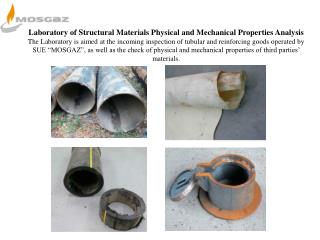
Modular Construction of Nuclear Plants • Structural Modules • Sub assemblies of the main building walls, floors, and ceilings. • Assembled on-site and lifted into place • Mechanical Modules • Structural Steel Frames • Contains Piping, Valves, Instruments, Conduit, Cable Trays, Ductwork, and equipment such as tanks, pumps, etc… • Fabricated off-site and transported to and installed on-site.
Mechanical Modules • A large structural rectangular frame • Module size is controlled by Transportation Limitations. • 12ft x 12ft x 80ft (3.7m x 3.7m x 24.4m) • 80 tons (73 metric tons) • Supports many mechanical components
Pipe / Valve Module 74147A
Sketch of module supporting cable tray, HVAC duct work, and piping
GTStrudl Model of module supporting cable tray, HVAC duct work, and piping
Design & Analysis of Mechanical Modules • Set of Drawings • Structural analysis software, GTStrudl. • Module design must be qualified for at least three conditions • Transportation • Lifting • Operation
Design Requirements • All applicable codes and standards must be followed. • Codes and standards must address all design requirements • Criteria may differ for different safety classifications of the module. • Safety related – Most stringent criteria • Quality related • Non-Safety related – Least stringent criteria
Special Modeling Techniques • Technique #1 • Create tables of Mechanical properties of equipment on module. • Cross sectional properties • Material properties • Maximum spans of piping, cable tray, conduit, and ductwork • Properties for transportation and lifting will be different from operation condition. • Water and insulation weight not included in Trans. & Lift. • Piping Modulus of Elasticity, E, should be reduced from the actual value for operation.
Technique #1 -- Tables of Properties Piping Properties
Special Modeling Techniques (cont.) • Technique #2 • Model continuation of commodities to one or two spans off module. • Simulates accurate dead weight and seismic loads onto the module . • Realistic forces and moments induced on members. • Reduce hand calculations.
Special Modeling Techniques (cont.) • Technique #3 • Accounting for off module thermal influences • In conjunction with technique #2 ensures accurate thermal expansion loads onto the module. • Results from external pipe stress analysis need not be considered if technique #3 is used conservatively.
Special Modeling Techniques (cont.) • Technique #4 • Accounting for piping operational loads • Use combined support design loads from the piping analyses instead of individual load case loads. • Will be a combination of all load cases • Accounts for dead weight, seismic, thermal, and any other loads on the on module piping. • Apply the maximum pipe support loads from seismic condition to the normal operation condition. • Consider the loads plus and minus to be conservative.
Special Modeling Techniques (cont.) • Technique #5 • Add conservatism to prepare for future modifications • Increase the component loads by 10-20% • Dead and live loads from piping, tanks, pumps, valves, etc… • Limit the stresses to 90% of allowable. • Member stresses, local stresses, and weld stresses. • Added conservatism should only be considered in the initial design phase and can be taken out during future analysis.
Designing for Transportation • Module must be designed with inherent rigidity since transportation poses a risk of damaging the module • Design the module to withstand certain designated accelerations in the direction of travel, lateral to travel, and vertical. • Using GTStrudl, create a model • Using Technique #1, add to the model all components attached to the module, such as piping, conduit, ductwork, cable tray, valves, pumps, etc… • Valves and Pumps should be modeled as rigid members • Piping, conduit, cable tray, etc. should be modeled as flexible according to their physical properties. • By including the components into the model, proper transportation effects can be simulated onto the structure. • The analysis must address structural member stresses, weld stresses, and local stresses for transportation load cases.
Designing for Lifting • Module will be lifted and installed into place using lifting lugs • Lifting Lugs should be designed using standard safety factors (SF = 2.0) applied to the maximum lifting lug load. • The model used for transportation can be used with lifting boundary conditions to calculate the maximum load acting on the lugs. • The analysis must address structural member stresses, weld stresses, and local stresses for lifting loads cases.
Designing for Operation • The off module piping, conduit, ductwork, and cable trays will apply loads to the module and should be modeled using the following techniques: • Use Technique #2 to model in the off-module spans of each item. • Use Technique #3 to apply conservative thermal expansion loads to the piping. • If loads from a pipe stress analysis are available, use Technique #4 to apply these loads as applied forces onto the module. • Techniques #5 should be used in all three conditions to add room for future modifications to the module. • The analysis must address structural member stresses, weld stresses, and local stresses for operation load cases.
Benefits of Using the Special Modeling Techniques • Provides accurate and conservative results. • Helps prevent major structural design modifications due to changes made during design finalization, procurement, or construction phases. • Provides significant savings in time and cost of construction.