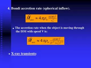
Chapter 4 Transients
Chapter 4 Transients. Electrical Engineering and Electronics II. Scott. 2008.9. Main Contents. 1. Solve first-order RC or RL circuits. 2. Understand the concepts of transient response and steady-state response. 3. Relate the transient response of first-order

Chapter 4 Transients
E N D
Presentation Transcript
Chapter 4 Transients Electrical Engineering and Electronics II Scott 2008.9
Main Contents 1. Solve first-order RC or RL circuits. 2. Understand the concepts of transient response and steady-state response. 3. Relate the transient response of first-order circuits to the time constant. 4. Solve RLC circuits in dc steady-state conditions.
Main Contents • Introduction • Initial state and DC Steady State • First-order RC Circuits • First-order RL Circuits • Summary
Conception of steady state and transient state R K R + Switch K is closed Us + _ E E _ C New steady state t Old steady state 4.1 Introduction When t=∞, uc(∞)=Us transient New steady state When t=0,uc(0)=0 Old steady state
Why the transient response happens? I t = 0 K No transient I + R E _ Resistance circuit • Resistor is a energy-consumption element, current is proportional to voltage, no transient response will happen even if changing source
K R + uC E _ C Electric field energy Charging or discharging Change gradually E t • Energy can not change instantly because of accumulating or decaying period.
K R t=0 + iL E _ E/R t Magnetic field energy Change gradually • Energy can not change instantly because of accumulating or decaying period.
Transients • The time-varying currents and voltages resulting from the sudden application of sources, usually due to switching. • By writing circuit equations, we obtain integrodifferential equations.
The causes of transients: 1. Energy storage elements -inductors and capacitors change gradually; 2.Changing circuit, such as switching source.
4.2 Initial state and steady state t=0+ t=0 t=0- t Assume changing circuit when t=0, then t=0– is end point of old steady state; t=0+ is the start point of transient state. The law of changing circuit From t=0–to t=0+,iL、uC change continuously.
DC Steady State Response • The steps in determining the forced response or steady state response for RLC circuits with dc sources are: • 1. Replace capacitances with open circuits. • 2. Replace inductances with short circuits. • 3. Solve the remaining circuit.
Example 4.1 Find steady-state values of vx and ix in this circuit for t>>0. Answer: vx =5V, ix = 1A t>>0
Exercise 4.3 Find steady-state values of labeled currents and voltages for t>>0. Answer: va =50V, ia = 2A i1 = 2A, i2=1A, i3=1A
How to get initial value Exercise 1: Assuming old circuit is in DC steady state before switch K is closed. how to get uC(0+),iR(0+)? R R K 1 1 4 k 4 k i R t =0 u u (0 ) 8k 12V C 12 V 8 k C – m 2 F R 2 Solution: When t=0-, capacitor is considered as open circuit, we get equivalent circuit. t=0-
How to get initial value R R K 1 1 4 k 4 k i i (0+) R R t =0 + u u (0 ) 8k 12V u (0+) C 12 V 8 k C – C m 2 F R – R 8k 2 2 t=0+ substituting voltage source for uC(0+)
How to get initial value • Exercise 2: Given by R1=4Ω, R2=6Ω, R3=3Ω, C=0.1µF, L=1mH, US=36V, switch S is closed for a long time. Open the switch S whent=0, how to get the initial values of all elements?
Equivalent circuit of First-order circuit Two parts: one (equivalent) capacitor or inductor; a two terminal network with resistance and sources. 4.3 First-order RC Circuits N N L C • First-order circuit Only one (equivalent) capacitor or inductor is included in a linear circuit. or
According to Thevenin Law N N C L iL iC + R + R uL L U uC C U - - 4.3 First-order RC Circuits or
Differential equation of first-order RC circuit iL iC + R + R uL L U uC C U - -
First-order RC Circuits • Example: to find the transient response after changing circuit when t=0. Solution:
First-order RC Circuits ——homogeneous solution ——particular solution
homogeneous solution • First-order RC Circuits
First-order RC Circuits • Particular solution Therefore Then, the final solution is
The solution of differential equation • First-order RC Circuits Substituting the initial condition:
The solution of differential equation • First-order RC Circuits ——Time constant ——Steady state value ——Initial value
Solution of other parameters • Three elements method Three elements: 1.steady state value f(∞); 2.time constant τ; 3. initial value f(0+).
Formula of Three element method: 4.3 First-order RL Circuits f(∞)——steady state value f(0+)——initial value τ——time constant τ=RC ——time constant of RC circuit τ= ?? ——time constant of RL circuit
Time constant iL iC + R + R uL L U uC C U - - 4.3 First-order RL Circuits τ=RC τ=L/R
Time constant reflects the length of transient period. • After one time constants, the transient response is equal to 36.8 percent of its initial value. • After about five time constants, the transient response is over.
The curves versus time • Time constant reflects the length of transient period. Mounting curve The initial slop intersects the final value at one time constant. Decaying curve
Three element method • Steps • Initial value: t=0-→t=0+ f(0+) • Steady state value: t =∞ f(∞) • Time constant : τ=RC τ=L/R • Substituting three elements • Draw the curve versus time • Limited Condition: 1) first-order circuit 2) DC source
Example 4.2 Find voltage of v(t) and current i(t) in this circuit for t>0. Answer:
Example 4.3 Find voltage of v(t) and current i(t) in this circuit for t>0. Answer:
Exercise 4.5 Find voltage of v(t) and current iR(t) , iL(t) in this circuit for t>0, assume that iL(0)=0. Answer:
Exercise 4.5 Find voltage of v(t) and current i(t), v(t) in this circuit for t>0, assume that the switch has been closed for a very long time prior to t=0. Answer:
Homework 4 • P4.8 • P4.18 • P4.26 • P4.30