Main Memory and Virtual Memory
Main Memory and Virtual Memory. Vincent H. Berk October 26, 2005 Reading for today: Sections 5.1 – 5.4, (Jouppi article) Reading for Friday: Sections 5.5 – 5.8 Reading for Monday: Sections 5.8 – 5.12 and 5.16. Main Memory Background. Performance of Main Memory:

Main Memory and Virtual Memory
E N D
Presentation Transcript
ENGS 116 Lecture 14 Main Memory and Virtual Memory Vincent H. Berk October 26, 2005 Reading for today: Sections 5.1 – 5.4, (Jouppi article) Reading for Friday: Sections 5.5 – 5.8 Reading for Monday: Sections 5.8 – 5.12 and 5.16
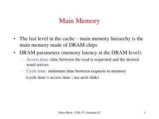
ENGS 116 Lecture 14 Main Memory Background • Performance of Main Memory: • Latency: Cache miss penalty • Access Time: time between request and word arrives • Cycle Time: time between requests • Bandwidth: I/O & large block miss penalty (L2) • Main Memory is DRAM: dynamic random access memory • Dynamic since needs to be refreshed periodically (1% time) • Addresses divided into 2 halves (memory as a 2-D matrix): • RAS or Row Access Strobe • CAS or Column Access Strobe • Cache uses SRAM: static random access memory • No refresh; 6 transistors/bit vs. 1 transistor; Size: DRAM/SRAM ≈ 4-8; Cost/Cycle time: SRAM/DRAM ≈ 8-16
ENGS 116 Lecture 14 4 Key DRAM Timing Parameters • tRAC: minimum time from RAS line falling to the valid data output. • Quoted as the speed of a DRAM when buying • A typical 512Mbit DRAM tRAC = 60-40 ns • tRC: minimum time from the start of one row access to the start of the next. • tRC = 80 ns for a 512Mbit DRAM with a tRAC of 60-40 ns • tCAC: minimum time from CAS line falling to valid data output. • 5 ns for a 512Mbit DRAM with a tRAC of 60-40 ns • tPC: minimum time from the start of one column access to the start of the next. • 15 ns for a 512Mbit DRAM with a tRAC of 60-40 ns
ENGS 116 Lecture 14 DRAM Performance • A 40 ns (tRAC) DRAM can • perform a row access only every 80 ns (tRC) • perform column access (tCAC) in 5 ns, but time between column accesses is at least 15 ns (tPC). • In practice, external address delays and turning around buses make it 20 to 25 ns • These times do not include the time to drive the addresses off the microprocessor or the memory controller overhead!
ENGS 116 Lecture 14 DRAM History • DRAMs: capacity + 60%/yr, cost – 30%/yr • 2.5X cells/area, 1.5X die size in ≈ 3 years • ‘98 DRAM fab line costs $2B • Rely on increasing numbers of computers & memory per computer (60% market) • SIMM or DIMM is replaceable unit computers use any generation DRAM • Commodity, second source industry high volume, low profit, conservative • Little organization innovation in 20 years • Order of importance: 1) Cost/bit, 2) Capacity • First RAMBUS: 10X BW, + 30% cost little impact • Current SDRAM yield very high: > 80%
ENGS 116 Lecture 14 Main Memory Performance • Simple: • CPU, Cache, Bus, Memory same width (32 or 64 bits) • Wide: • CPU/Mux 1 word; Mux/Cache, Bus, Memory N words (Alpha: 64 bits & 256 bits; UltraSPARC 512) • Interleaved: • CPU, Cache, Bus 1 word; Memory N modules (4 modules); example is word interleaved
Address Bank 0 Address Bank 1 Address Bank 2 Address Bank 3 0 4 8 12 1 5 9 13 2 6 10 14 3 7 11 15 ENGS 116 Lecture 14 Main Memory Performance • Timing model (word size is 32 bits) • 1 to send address, • 6 for access time, 1 to send data • Cache Block is 4 words • Simple memory 4 (1 + 6 + 1) = 32 • Wide memory 1 + 6 + 1 = 8 • Interleaved memory 1 + 6 + 4 1 = 11
... ENGS 116 Lecture 14 Independent Memory Banks • Memory banks for independent accesses vs. faster sequential accesses • Multiprocessor • I/O (DMA) • CPU with Hit under n Misses, Non-blocking Cache • Superbank: all memory active on one block transfer (or Bank) • Bank: portion within a superbank that is word interleaved (or subbank) Superbank Superbank offset (Bank) Superbank # Bank offset Bank #
ENGS 116 Lecture 14 Independent Memory Banks • How many banks? number banks ≥ number clocks to access word in bank • For sequential accesses, otherwise will return to original bank before it has next word ready • (like in vector case) • Increasing DRAM fewer chips harder to have banks
ENGS 116 Lecture 14 Avoiding Bank Conflicts • Lots of banks int x[256][512]; for (j = 0; j < 512; j = j+1) for (i = 0; i < 256; i = i+1) x[i][j] = 2 * x[i][j]; • Even with 128 banks, since 512 is multiple of 128, conflict on word accesses • SW: loop interchange or declaring array not power of 2 (“array padding”) • HW: prime number of banks • bank number = address mod number of banks • address within bank = address / number of words in bank • modulo & divide per memory access with prime no. banks? • address within bank = address mod number words in bank • bank number? easy if 2N words per bank
ENGS 116 Lecture 14 Fast Memory Systems: DRAM specific • Multiple CAS accesses: several names (page mode) • Extended Data Out (EDO): 30% faster in page mode • New DRAMs to address gap; what will they cost, will they survive? • RAMBUS: startup company; reinvent DRAM interface >> Each chip a module vs. slice of memory >> Short bus between CPU and chips >> Does own refresh >> Variable amount of data returned >> 1 byte / 2 ns (500 MB/s per chip) • Synchronous DRAM: 2 banks on chip, a clock signal to DRAM, transfer synchronous to system clock (66 - 150 MHz) • Intel claims RAMBUS Direct is future of PC memory • Niche memory or main memory? • e.g., Video RAM for frame buffers, DRAM + fast serial output
ENGS 116 Lecture 14 Virtual Memory Virtual Address (232, 264) to Physical Address mapping (228) Virtual memory in terms of cache: Cache block? Cache miss? How is virtual memory different from caches? What controls replacement Size (transfer unit, mapping mechanisms) Lower-level use
Virtual address: Physical address: 0 4K 0 8K 4K Physical main memory 12K 8K 12K Virtual memory 16K 20K A 24K C B 28K C D A D Disk B ENGS 116 Lecture 14 Figure 5.36 The logical program in its contiguous virtual address space is shown on the left; it consists of four pages A, B, C, and D.
Figure 5.37 Typical ranges of parameters for caches and virtual memory. ENGS 116 Lecture 14
ENGS 116 Lecture 14 Virtual Memory • 4 Questions for Virtual Memory (VM)? • Q1: Where can a block be placed in the upper level? fully associative, set associative, or direct mapped? • Q2: How is a block found if it is in the upper level? • Q3: Which block should be replaced on a miss? random or LRU? • Q4: What happens on a write? write back or write through? • Other issues: size; pages or segments or hybrid
Virtual address Virtual page number Page offset Main memory Page table Physical address ENGS 116 Lecture 14 Figure 5.40 The mapping of a virtual address to a physical address via a page table.
Page offset <13> Page-frame address <30> <30> Tag <21> Physical page # 1 <1> <2><2> 2 V R W (low-order 13 bits of address) <13> 34-bit physical address 32:1 MUX 4 3 <21> (high-order 21 bits of address) ENGS 116 Lecture 14 Fast Translation: Translation Buffer (TLB) • Cache of translated addresses • Data portion usually includes physical page frame number, protection field, valid bit, use bit, and dirty bit • Alpha 21064 data TLB: 32-entry fully associative
ENGS 116 Lecture 14 Selecting a Page Size • Reasons for larger page size • Page table size is inversely proportional to the page size; therefore memory saved • Fast cache hit time easy when cache ≤ page size (VA caches); bigger page makes it feasible as cache grows in size • Transferring larger pages to or from secondary storage, possibly over a network, is more efficient • Number of TLB entries is restricted by clock cycle time, so a larger page size maps more memory, thereby reducing TLB misses • Reasons for a smaller page size • Fragmentation: don’t waste storage; data must be contiguous within page • Quicker process start for small processes • Hybrid solution: multiple page sizes • Alpha: 8 KB, 16 KB, 32 KB, 64 KB pages (43, 47, 51, 55 virtual addr bits)
Page Table Base Register + + + Page table entry Page table entry Page table entry Physical address physical page-frame number page offset ENGS 116 Lecture 14 Alpha VM Mapping 21 Virtual address seg0/seg1 selector 000 … 0 or 111 … 1 level1 level2 level3 page offset 10 10 10 13 • “64-bit” address divided into 3 segments • seg0 (bit 63 = 0) user code/heap • seg1 (bit 63 = 1, 62 = 1) user stack • kseg (bit 63 = 1, 62 = 0) kernel segment for OS • Three level page table, each one page • Alpha only 43 bits of VA • (future min page size up to 64 KB 55 bits of VA) • PTE bits; valid, kernel & user, read & write enable (no reference, use, or dirty bit) • What do you do? L1 page table . . . L2 page table . . . L3 page table . . . . . . . . . . . . 8 bytes 32 bit address 32 bit fields Main memory
ENGS 116 Lecture 14 Protection • Avoid separate processes to access each others memory • Causes Segmentation Fault: sigSEG • Useful for Multitasking systems • Operating system issue • At least two levels of protection: • Supervisor (Kernel) mode (privileged) • Creates page tables, sets process bounds, handles exceptions • User mode (non-privileged) • Can only make requests to Kernel: called SYSCALLs • Shared memory • SYSCALL parameter passing
ENGS 116 Lecture 14 Protection 2 • Each page needs: • PID bit • Read/Write/Execute bit • Each process needs • Stack frame page(s) • Text or code pages • Data or heap pages • State table keeping: • PC and other CPU status registers • State of all registers
ENGS 116 Lecture 14 Alpha 21064 • Separate Instruction & Data TLB & Caches • TLBs fully associative • TLB updates in SW(“Private Arch Lib”) • Caches 8KB direct mapped, write through • Critical 8 bytes first • Prefetch instr. stream buffer • 2 MB L2 cache, direct mapped, WB (off-chip) • 256 bit path to main memory, 4 64-bit modules • Victim buffer: to give read priority over write • 4-entry write buffer between D$ & L2$ Data Instr Write Buffer Stream Buffer Victim Buffer
ENGS 116 Lecture 14 Alpha CPI Components • Instruction stall: branch mispredict (green); • Data cache (blue); Instruction cache (yellow); L2$ (pink) Other: compute + register conflicts, structural conflicts
ENGS 116 Lecture 14 Pitfall: Predicting Cache Performance of One Program from Another (ISA, compiler, ...) 35% • 4KB data cache: miss rate 8%, 12%, or 28%? • 1KB instruction cache: miss rate 0%, 3%, or 10%? • Alpha vs. MIPSfor 8 KB Data $:17% vs. 10% • Why 2X Alpha v. MIPS? D$, Tom 30% D: tomcatv D: gcc 25% D: espresso I: gcc D$, gcc I: espresso 20% I: tomcatv Miss Rate D$, esp 15% 10% I$, gcc 5% I$, esp 0% 1 2 4 8 16 32 64 128 I$, Tom Cache Size (KB)
ENGS 116 Lecture 14 Pitfall: Simulating Too Small an Address Trace 4.5 4 Cumulative Average Memory Access Time 3.5 3 2.5 2 1.5 1 0 1 2 3 4 5 6 7 8 9 10 11 12 I$ = 4 KB, B = 16 B D$ = 4 KB, B = 16 B L2 = 512 KB, B = 128 B MP = 12, 200 (miss penalties) Instructions Executed (billions)
ENGS 116 Lecture 14 Additional Pitfalls • Having too small an address space • Ignoring the impact of the operating system on the performance of the memory hierarchy
ENGS 116 Lecture 14 Figure 5.53 Summary of the memory-hierarchy examples in Chapter 5.