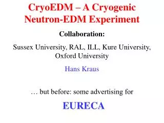
The cryogenic neutron EDM experiment at ILL
460 likes | 628 Vues
The cryogenic neutron EDM experiment at ILL. Technical challenges and solutions. James Karamath University of Sussex. In this talk…. (n)EDM motivation Measurement principles and sensitivity Brief (recent) nEDM history The Cryo-EDM experiment Overview of apparatus Summary of my DPhil work

The cryogenic neutron EDM experiment at ILL
E N D
Presentation Transcript
The cryogenic neutron EDM experiment at ILL Technical challenges and solutions James Karamath University of Sussex
In this talk… • (n)EDM motivation • Measurement principles and sensitivity • Brief (recent) nEDM history • The Cryo-EDM experiment • Overview of apparatus • Summary of my DPhil work • Summary/conclusions James Karamath University of Sussex 09/09/2014 07:23:15
(n)EDMs – so? I S S + + d d - - • P- and T-violating • CPV in SM not fully understood e.g. insufficient CPV for baryon asymmetry • Strong CP problem • θCP < 10-10 rad. Axions? g p × p n n James Karamath University of Sussex 09/09/2014 07:23:15
g squark quark electric dipole moments: q q gaugino (n)EDMs – so? II • Estimated EDMs model dependent • SM dn ~ 10-31ecm • Other models typically 105-6 times greater • e.g. SUSY: CP< 10-2
nEDM measurement principle B0 B0 B0 E E <Sz> = + h/2 h()= 2(-μ.B-dn.E) h()= 2(-μ.B+dn.E) h(0) = -2μ.B <Sz> = - h/2 dn defined +ve ↑↑ - ↑↓= Δ = 4dn.E / h Ramsey NMR performed on stored Ultra Cold Neutrons (UCN)
Ramsey’s method of separated fields Start with spin polarised neutrons in uniform B-field (Bz) Apply oscillating B-field pulse (Bxy) perpendicular to Bz. Precession axis rotates down to xy-plane Apply large E-field and allow to precess freely for ~300s Apply 2nd, phase coherent with the first, oscillating Bxy. Neutron precession axis rotates down to –z axis.
Ramsey’s method of separated fields However if an EDM is present a phase difference builds up during the free precession If 180 out of phase second pulse returns spin back to +z axis.
Ramsey’s method of separated fields (2n-1)π out of phase Experimental runs taken at approx π/2 off resonance. Here dN/dν is a maximum.
nEDM statistical limit • Fundamental statistical limit α = visibility [polarisation product] E = E-field strength T = NMR coherence time N = total # counted James Karamath University of Sussex 09/09/2014 07:23:15
nEDM systematic limit • Main concern: changes in B-field accidentally correlated with E-field changes give false dn signal h(ν↑↑–ν ↑↓) = 2|μn|(B↑↑–B↑↓) – 4dnE True nEDM signal False signal due to varying B
Beam era ΔB ≈ v x E / c2 limited RT stored UCN era nEDM experiments: history Co-magnetometer era Cryogenic UCN era
B E RT nEDM experiment at ILL Magnetic shielding • Create UCN, can then be guided & stored • Polarise UCN • UCN admitted into cell with E and B-fields and stored… • Mercury polarised by Hg lamp and added to cell High voltage lead Magnetic field coil Storage cell Approx scale 1 m Magnet &polarizing foil /analysing foil S N UCN James Karamath University of Sussex 09/09/2014 07:23:15
B E RT nEDM experiment at ILL Magnetic shielding • Ramsey NMR performed • Released from cell • Neutrons spin analysed (# fn of precession) • Mercury spin analysed. • Repeat: E=↓or 0, B=↓ High voltage lead Magnetic field coil Storage cell Approx scale 1 m Magnet & polarizing foil/ analysing foil S N UCN detector James Karamath University of Sussex 09/09/2014 07:23:15
Magnetometer problems Systematics I • Mercury fills cell uniformly, UCN sag under gravity, lower by ~3 mm. • Thus don’t sample EXACTLY the same B-field. Axial (z) gradients → problems… z n Hg James Karamath University of Sussex 09/09/2014 07:23:15
Geometric Phase Effect (GPE) Systematics II • Two conspiring effects • v x E: motional particle in electric field experiences B-field: ΔB ≈v x E / c2 • Axial field gradient dB/dz creates radial B-field (since .B=0) proportional to r, Br r • Let’s look at motion of a mercury atom across the storage cell
Geometric Phase Effect (GPE) Systematics III Scales with E like EDM!!! B v x E Scales with dB/dz dB/dz → B r i.e. B0 field into page has gradient (GPEHg ~ 40GPEn) Resultant Rotating B field Using Mercury introduces error Shifts resonance of particle E and B0 into page
www.neutronedm.org Final result • Room temperature experiment gave the result; dn = (+0.61.5(stat) 0.8(syst)) x 10-26) ecm i.e. |dn| < 3.0 x 10⁻²⁶ecm (90% CL). • New cryogenic experiment will eventually be x100 more sensitive…
The Cryogenic nEDM experiment • Reminder: * x20 x5* x2 ~10-28ecm x1.2 x2 *with new beamline
Improved production of UCN (↑N) I • Crosses at 0.89 nm for free (cold) n. Neutron loses all energy by phonon emission → UCN. • Reverse suppressed by Boltzmann factor, He-II is at 0.5K, no 12K phonons. Dispersion curves for He-II and free neutrons James Karamath University of Sussex 09/09/2014 07:23:15
Improved production of UCN (↑N) II • Idea by Pendlebury and Golub in 1970’s, experimentally verified in 2002 (detected in He-II) for cold neutron beam at ILL (~1 UCN/cm3/sec). • Also better guides – smoother & better neutron holding surfaces, Be / BeO / DLC coated → more neutrons guided/stored. Allows longer T too. James Karamath University of Sussex 09/09/2014 07:23:15
Polarisation and detection (α) I • Polarisation by Si-Fe multi-layer polarizer, 95±6% initial polarisation. • Can lose polarisation in 2 ways: • “Wall losses” magnetic impurities in walls, generally not aligned with neutron spin • Gradients in B-field, if not smooth and steady have similar effect James Karamath University of Sussex 09/09/2014 07:23:15
Polarisation and detection (α) II • Detector: solid state, works in 0.5K He-II. • n (6Li, α) 3H reaction - alpha or triton detected • Thin, polarised Fe layer - spin analysis James Karamath University of Sussex 09/09/2014 07:23:15
Magnetic field issues I Shielding factors • Target – need ~ 100 fT stability (NMR) • Need ~ 1 nT/m spatial homogeneity (GPE) • Perturbations ~ 0.1 μT (cranes!) • Need (axial) shielding factor ~ 106 • Mu-metal shielding ~ 50 • Superconducting shielding ~ 8x10⁵ • Active shielding (feedback coils) ~ 15
Magnetic field issues II Extra benefits • CRYOGENIC nEDM! Utilise superconducting shield and B0 solenoid. • Major part of fluctuations across whole chamber (common mode variations) • Magnetometer (zero E-field) cell(s) see same • Very stable B0(t) current • Holding field x5 to reduce GPE of the neutrons by factor of 25 (GPEn 1/B02) James Karamath University of Sussex 09/09/2014 07:23:15
Magnetic field issues III SQUIDS • ~fT sensitivity • 12 pickup loops will sit behind grounded electrodes. • Will show temporal stability of B-field at this level. • Additional sensitivity from zero-field cell(s)
Improving the E-field (↑E) I: The HV • Now have a 400 kV supply to connect to HV electrode. • Will sit in 3bar SF6. For 160 kV use N2:CO2 first. James Karamath University of Sussex 09/09/2014 07:23:15
Improving the E-field (↑E) II: HV line 1 400 kV bipolar stack 50 kV ~1 GOhm resistors Superfluid containment vessel (SCV) HV electrode Ground electrodes N.B. Diamond-like-carbon coated titanium electrodes BeO spacers
Improving the E-field (↑E) II: HV line 2 Thick walled PTFE tube and thin-walled SS tube HV “cryo-cable”. Spellman +130 kV Spellman -130 kV Standard 150 kV cable HV connection
The dielectric strength of LHe • Has been tested in the past, mostly at 4.2 K (760 torr), at small electrode gaps (sub-mm) and with small electrodes. Superfluid data is limited and generally at low voltages (sub-40 kV, often sub-20 kV). • Usually the breakdown strength as a function of gap is studied. We’d like to know the strength as the pressure/temperature falls – esp. in the superfluid state. James Karamath University of Sussex 09/09/2014 07:23:15
Past literature The dielectric strength of LHe II He-I data 4.2 < T(K) < 2.2 Nope – put in the final versions from thesis
Past literature The dielectric strength of LHe III He-II data 2.2 < T(K) < 1.4
Sussex HV tests The dielectric strength of LHe IV ±HV • Test electrodes submerged in He-II in bath cryostat. • Studying Vbd and Ileak as function of d, T, dielectric spacers, purity… up to 130 kV. Also electrode damage. E cryostat gap (d, V, spacers) He-II (T, purity…)
Sussex HV results The dielectric strength of LHe IV
Statistics The dielectric strength of LHe VI
The dielectric strength of LHe VII • Size effects: Weak but important dependence on electrode area or stressed fluid volume may decrease dielectric strength. • Leakage currents never found to be >0.1 nA (sensitivity limited) even immediately below breakdown. • ~0.3 mm craters in electrodes when breakdown occurs at >80 kV. Bad news for DLC coated electrodes.
The dielectric strength of LHe VI • Breakdown strength reduced by insulating BeO spacers by a factor of ~1.4. Due to surface tracking along the BeO.
The dielectric strength of LHe summary • At 0.7 cm gap the breakdown field strength was approx 80 ± 10 kV/cm. i.e. ~50 kV/cm for 1 in 1000 chance of breakdown. May have to half this if size effects indeed exist. • What controls breakdown – pressure or temperature?! May hold key to improving Vbd.
And so, the CryoEDM experiment I E ~ 25kV/cm n guide tubes + spin analyser E = 0kV/cm Spin flipper coil (measure other spin)
HV electrode HV in Carbon fibre support BeO spacers Ground electrodes And so, the CryoEDM experiment II z
G10 Superfluid containment vessel HV in HV electrode * * Neutrons in/out Guides not shown Ground electrodes *BeO spacers/guides And so, the CryoEDM experiment III z 250l He-II 0.5K
The shielded region 1m And so, the CryoEDM experiment IV Dynamic shielding coils Magnetic (mu-metal) shields Superconducting shield and solenoid
Schedule / Future • Finish construction THIS YEAR • Start data taking THIS YEAR • First results ~2009 • Upgrade neutron guide to ↑N ~2009 ? James Karamath University of Sussex 09/09/2014 07:23:15
Summary • (n)EDMs help study T-violation and are constraining new physics. • Final RT result: |dn| < 3.0 x 10⁻²⁶ecm. • Aim to push well into 10-28ecm. • Further work needed to understand dielectric properties of He-II. Only 20 kV/cm? (Paper in preparation.) Can pressure/purity/electrode material make a difference?
Done! • Thanks for listening