Precision Variable Frequency Drive May 07-13
Precision Variable Frequency Drive May 07-13. Client: Jim Walker Advisor: Dr. Ajjarapu Team Members: Matt Shriver Jason Kilzer Nick Nation Dave Reinhardt April 24, 2007. Presentation Outline. Introductory Materials (Nick) Project Approach & Design (Jason) Testing and Implementation (Matt)

Precision Variable Frequency Drive May 07-13
E N D
Presentation Transcript
Precision Variable Frequency DriveMay 07-13 Client: Jim WalkerAdvisor: Dr. AjjarapuTeam Members:Matt ShriverJason KilzerNick NationDave ReinhardtApril 24, 2007
Presentation Outline • Introductory Materials (Nick) • Project Approach & Design (Jason) • Testing and Implementation (Matt) • Closing Materials (Dave)
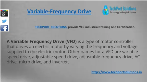
List of Definitions • VFD: Variable Frequency Drive • PWM: Pulse Width Modulation • IGBT: Insulated Gate Bipolar Transistor
Acknowledgements • Faculty advisor Dr. Ajjarapu • Client Jim Walker • Graduate Students • Ryan Konopinski • Sheng Yang
General Problem Statement • The speed control of an AC synchronous motor. • The synchronous motor and the subsequent drive mechanism do not always keep the correct speed. • A method is needed to control the frequency that is delivered to the synchronous motor.
Solution • A precision variable frequency drive will allow the user to manually change the operating frequency.
Operating Environment • Indoors • No extreme conditions • Near power outlet
Intended Use • As a drive for a low power AC synchronous electric motor. • This drive was not considered to be used on any other type of electric motor except for a synchronous design. • This drive shall not be used to power any control circuits.
Intended Users • Anyone who desires precise control over a small AC synchronous motor. • An owner of a turntable who needs better control over the speed of their turntable. • No technical knowledge will be required to operate the Precision VFD.
Assumptions • Constant linkage –An increase in motor speed by a certain factor will result in an increase in the speed of the turntable by the same factor. • Plug – the power cord from the record player can plug into a standard three pronged outlet.
Limitations • Minimum Power Output: 75 W • Output Frequency Range: 58-62 Hz • Frequency Precision: 0.001 Hz • Frequency Stability: < ± 0.01 % • 12” by 12” by 6” size limitation • Cost less than $350
Expected End Product • Precision variable frequency drive • Portable strobe system • One-page quick users guide • Circuit diagrams and parts list
Present Accomplishments • Research technologies (100%) • Simulate entire system (100%) • Purchase components (100%) • Build components (85%) • Test components (70%) • Build entire system (70%)
Project Definition Activities • Develop a VFD that will provide a precise frequency that can be changed. • A strobe light will also be included to measure the RPM of the electric motor.
Research Activities (1 of 2) • Pulse Width Modulation • Needs small signal variable frequency sine wave • Need small signal triangle wave • Comparator produce pulses from comparison of sine and triangle wave • PWM would create the control signals for the IGBT bridge
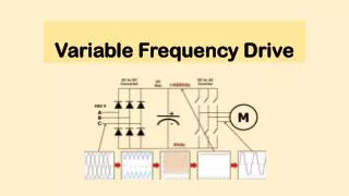
Research Activities (2 of 2) • IGBT Bridge • Provides power separation between PWM circuits and power supply circuitry • Generates pulses
Precision Variable Frequency Drive • Ready to use design • Delivers precise frequency control for low power AC synchronous motors • Strobe light included to measure RPM of motor
Design • Pulse Width Modulation Circuits • IGBT Bridge and Filter Circuits • Power Supply Circuits
Power Supply Components • Astrodyne Power Supply (PT-45C) • Input: 120 VAC • Outputs: +/-15V, +5V • Filament Transformer • Primary Winding: 117V • Secondary Winding: 8V
Filter Input/Output Waveforms Input and Output Waveforms of the Low Pass Filter
Implementation and Testing • Function generator chips • Amplifiers • Comparator and Inverter • IGBT’s • Filter • Strobe light system
Sine & Triangle Generator Chips • Built and tested on breadboard
Amplifiers, Comparator, and Inverter Circuits • Built and tested on breadboard
Comparator Testing Comparator Chips • UA741 Op Amp • LM319N High Speed Comparator Sources • Lab Function Generators • Function Generator Chips
IGBT Bridge • build and test on breadboard
IGBT Bridge Testing • Design overlooked need for delay circuitry • Tried multiple timing circuits • NE555 Timer Circuit • UA741 Op Amp Circuit
Strobe Light System Strobe Light Schematic
Schedule Detailed Gantt Chart
Deadline Schedule Deadlines Schedule
Commercialization • Not produced for commercialization • Precision variable frequency drive could be implemented for much less than current market price (~$250)
Additional Work • Resolve comparator issues • Resolve IGBT issues • Combine Precision VFD and strobe light system into one product • Include feedback loop for total autonomy
Lessons Learned (1 of 2) • What went well • Design/Simulation of project • Testing • What did not go well • Problem definition and planning (needed a new plan when we started implementing) • Having everyone on the same page (team members, advisor, vendor)
Lessons Learned (2 of 2) • Technical • Implement and test one component at a time • Keep it simple • Comparator troubleshooting • IGBT implementation • Non-technical • Should have planned a lot more time for implementation • Everyone must be on the same page • Have a good plan to start