Download
1 / 121
1.66k likes | 2.17k Vues
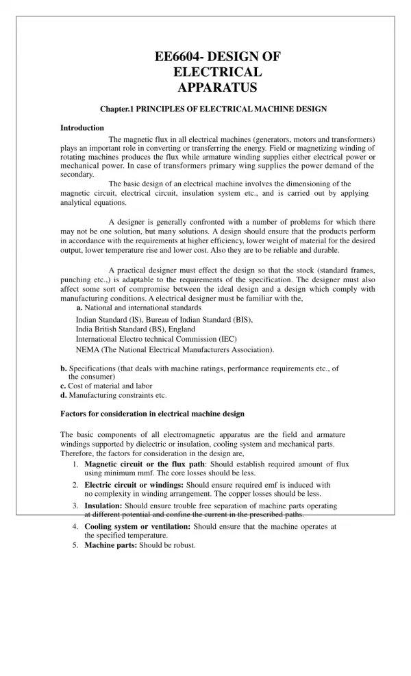
EE6604- DESIGN OF ELECTRICAL APPARATUS Chapter.1 PRINCIPLES OF ELECTRICAL MACHINE DESIGN Introduction The magnetic flux in all electrical machines (generators, motors and transformers)

E N D
EE6604- DESIGN OF ELECTRICAL APPARATUS Chapter.1 PRINCIPLES OF ELECTRICAL MACHINE DESIGN Introduction The magnetic flux in all electrical machines (generators, motors and transformers) playsanimportantroleinconvertingortransferringtheenergy.Fieldormagnetizingwindingof rotatingmachinesproducesthefluxwhilearmaturewindingsupplieseitherelectricalpoweror mechanical power. In case of transformers primary wing supplies the power demand of the secondary. The basic design of an electrical machine involves the dimensioning of the magnetic circuit, electrical circuit, insulation system etc., and is carried out by applying analytical equations. Adesignerisgenerallyconfrontedwithanumberofproblemsforwhichthere maynotbeonesolution,butmanysolutions.Adesignshouldensurethattheproductsperform in accordancewith therequirements at higherefficiency, lower weight ofmaterial forthedesired output, lower temperature rise and lower cost. Also theyareto bereliableand durable. A practical designer must effect the design so that the stock (standard frames, punching etc.,) is adaptable to the requirements of the specification. The designer must also affect some sort of compromise between the ideal design and a design which comply with manufacturing conditions. A electrical designer must be familiar with the, a. National and international standards Indian Standard (IS), Bureau of Indian Standard (BIS), India British Standard (BS), England International Electro technical Commission (IEC) NEMA (The National Electrical Manufacturers Association). b. Specifications (that deals with machine ratings, performance requirements etc., of the consumer) c. Cost of material and labor d. Manufacturing constraints etc. Factors for consideration in electrical machine design The basic components of all electromagnetic apparatus are the field and armature windings supported by dielectric or insulation, cooling system and mechanical parts. Therefore, the factors for consideration in the design are, 1. Magneticcircuitorthefluxpath:Shouldestablishrequiredamountofflux usingminimum mmf. The corelosses should beless. 2. Electriccircuitorwindings:Shouldensurerequiredemfisinducedwith no complexityin windingarrangement. Thecopper losses should beless. 3. Insulation:Shouldensuretroublefreeseparationofmachinepartsoperating at different potential andconfinethe current in theprescribed paths. 4. Coolingsystemorventilation:Shouldensurethatthemachineoperatesat the specifiedtemperature. 5. Machineparts: Should be robust.
The art of successful design lies not only in resolving the conflict for space between iron, copper, insulation and coolant but also in optimization of cost of manufacturing, and operating and maintenance charges. The factors, apart from the above, that requires consideration are a. Limitation in design ( saturation, current density, insulation, temperaturerise etc.,) b. Customer’s needs c. National and international standards d. Conveniencein production line and transportation e. Maintenance and repairs f. Environmental conditions etc. Limitations in design The materials used for the machine and others such as cooling etc., imposes a limitation in design. The limitations stem from saturation of iron, current density in conductors, temperature, insulation, mechanical properties, efficiency, power factor etc. a. Saturation:Higherfluxdensityreducesthevolumeofironbutdrivestheironto operatebeyondknee of themagnetizationcurve or intheregionofsaturation. Saturationofironposesa limitationonaccountofincreasedcorelossandexcessive excitation required to establish a desired valueofflux. Italso introduces harmonics. b. Currentdensity:Highercurrentdensityreducesthevolumeofcopperbutincreases the losses and temperature. c. Temperature:posesalimitationonaccountofpossibledamagetoinsulationand othermaterials. d. Insulation(whichisbothmechanicallyandelectricallyweak):posesalimitationon account of breakdown byexcessive voltagegradient, mechanical forces orheat. e. Mechanicalstrengthofthematerialsposesalimitationparticularlyincaseoflarge and high speed machines. fHighefficiencyandhighpowerfactorposesalimitationonaccountofhighercapital cost.(Alowvalueofefficiency andpowerfactorontheotherhandresultsinahigh maintenancecost). g. Mechanical Commutationin dc motors orgenerators leads to poor commutation. ApartfromtheabovefactorsConsumer,manufacturerorstandardspecificationsmay pose alimitation.
Materials for Electrical Machines The main material characteristics of relevance to electrical machines are those associated with conductors for electric circuit, the insulation system necessary to isolate the circuits, and with the specialized steels and permanent magnets used for the magnetic circuit. Conducting materials Commonly used conducting materials are copper and aluminum. Some of the desirable properties a good conductor should possess are listed below. 1. Low value ofresistivityorhigh conductivity 2. Low value oftemperature coefficient ofresistance 3. High tensilestrength 4. High meltingpoint 5. High resistanceto corrosion 6. Allow brazing, soldering orweldingso that thejoints are reliable 7. Highlymalleable and ductile 8. Durable andcheap bycost Some of the properties of copper and aluminum are shown in the table-2. Table-2 Sl. Particulars Copper Aluminum 1 Resistivityat200C 0.0172 ohm/m/mm2 0.0269 ohm/m/mm2 3 Densityat200C 8933kg/m3 2689.9m3 C (0-100oC) resistanceincreases by0.4% in caseofaluminum expansion (0-100oC) 6 Tensilestrength 25 to 40 kg/mm 10 to 18 kg/mm 7 Mechanical property highlymalleableand not highlymalleable and ductile ductile 8 Meltingpoint 1083C 660C (0-100oC) 10 Jointing can beeasilysoldered cannot be soldered easily No 2 Conductivity at 200C 58.14 x 10⁶S/m 37.2 x 10⁶S/m 4 Temperature coefficient 0.393 % per 0C 0.4 % per 0 Explanation: If the temperature increases by 1oC, the 5 Coefficient of linear 16.8x10⁻⁶ per oC 23.5 x10⁻⁶ per oC 2 2 0 0 9 Thermal conductivity 599 W/m 0C 238 W/m 0C
For the same resistance and length, cross-sectional area of aluminum is 61% larger than that of the copper conductor and almost 50% lighter than copper. Thoughthealuminumreducesthecostofsmallcapacity transformers,itincreasesthesizeand costoflargecapacity transformers.Aluminumisbeingmuchusednowadaysonlybecause copperisexpensiveandnoteasilyavailable.Aluminumisalmost50%cheaperthanCopper and not much superiortocopper. Magnetic materials The magnetic properties of a magnetic material depend on the orientation of the crystals of the material and decide the size of the machine or equipment for a given rating, excitation required, efficiency of operation etc. . The some of the properties that a good magnetic material should possess are listed below. 1. Lowreluctanceorshouldbehighlypermeableorshouldhaveahighvalueofrelative permeabilityr. 2. High saturation induction (to minimizeweight andvolumeof iron parts) 3. High electrical resistivityso that the eddyemf andthe henceeddycurrent loss is less 4. NarrowhysteresislooporlowCoercivitysothat hysteresislossis lessand efficiencyof operation is high 5. A high curiepoint. (AboveCurie point or temperaturethe material loses themagnetic property or becomes paramagnetic, that is effectively non-magnetic) Magnetic materials can broadly be classified as Diamagnetic, Paramagnetic, Ferromagnetic, Antiferromagnetic and Ferrimagnetic materials. Only ferromagnetic materials have properties that are well suitable for electrical machines. Ferromagnetic properties are confined almost entirely to iron, nickel and cobalt and their alloys. The only exceptions are some alloys of manganese and some of the rare earth elements. The relative permeability r of ferromagnetic material is far greater than 1.0. When direction of the applied field and get strongly magnetized. Further theFerromagnetic materialscanbe classifiedasHard or PermanentMagnetic materials and Soft Magneticmaterials. a) Hard or permanent magnetic materials have large size hysteresis loop (obviously hysteresis loss is more) and gradually rising magnetization curve. Ex: carbon steel, tungsten steal, cobalt steel, alnico, hard ferrite etc. b) Soft magnetic materials have small size hysteresis loop and a steep magnetization curve. Ex: i) cast iron, cast steel, rolled steel, forged steel etc., (in the solid form). - Generally used for yokes poles of dc machines, rotors of turbo alternator etc., where steady or dc flux is involved. 6. Should have a high value of energy product (expressed in joules / m3). ferromagnetic materials are subjected to the magnetic field, the dipoles align themselves in the
ii) Silicon steel (Iron + 0.3 to 4.5% silicon) in the laminated form. Addition of silicon in proper percentage eliminates ageing & reduce core loss. Low silicon content steel or dynamo grade steel is used in rotating electrical machines and are operated at high flux density. High content silicon steel (4 to 5% silicon) or transformer grade steel (or high resistance steel) is used in transformers. Further sheet steel may be hot or cold rolled. Cold rolled grain oriented steel (CRGOS) is costlier and superior to hot rolled. CRGO steel is generally used in transformers. c) Special purpose Alloys: Nickel iron alloys have high permeability and addition of molybdenum or chromium leads to improved magnetic material. Nickel with iron in different proportion leads to (iHigh nickel permalloy (iron +molybdenum +copper or chromium), used in current transformers, magnetic amplifiers etc., (iiLow nickel Permalloy (iron +silicon +chromium or manganese), used in transformers, induction coils, chokes etc. (iii) Perminvor (iron +nickel +cobalt) (iv) Pemendur (iron +cobalt+vanadium), usedformicrophones, oscilloscopes,etc. (v) Mumetal (Copper +iron) d) Amorphous alloys (often called metallic glasses): Amorphous alloys are produced by rapid solidification of the alloy at cooling rates of about a million degrees centigrade per second. The alloys solidify with a glass-like atomic structure which is non-crystalline frozen liquid. The rapid cooling is achieved by causing the molten alloy to flow through an orifice onto a rapidly rotating water cooled drum. This can produce sheets as thin as 10µm and a metre or more wide. These alloys can be classified as iron rich based group and cobalt based group. Maximum Saturation Coercivity Curie Resistivity µx10-3 intesla oC 3% Si grain oriented 90 2.0 6-7 745 48 2.5%Si grain non-oriented 8 2.0 40 745 44 <0.5%Si grain non oriented 8 2.1 50-100 770 12 Lowcarboniron 3-10 2.1 50-120 770 12 78%Ni and iron 250-400 0.8 1.0 350 40 50%Ni and iron 100 1.5-1.6 10 530 60 Iron basedAmorphous 35-600 1.3-1.8 1.0-1.6 310-415 120-140 Material permeability magnetization A/m temperature m x 108
Insulating materials To avoid any electrical activity between parts at different potentials, insulation is used. An ideal insulating material should possess the following properties. 1) Should have high dielectric strength. 2) Should with stand high temperature. 3) Should have good thermal conductivity 4) Should not undergo thermal oxidation 5) Should not deteriorate due to higher temperature and repeated heat cycle 7) Should not consume any power or should have a low dielectric loss angle δ 8) Should withstand stresses due to centrifugal forces ( as in rotating machines), electro dynamic or mechanical forces ( as in transformers) 9) Should withstand vibration, abrasion, bending 10) Should not absorb moisture 11) Should be flexible and cheap 12) Liquid insulators should not evaporate or volatilize Insulating materials can be classified as Solid, Liquid and Gas, and vacuum. The term insulting material is sometimes used in a broader sense to designate also insulating liquids, gas and vacuum. Solid: Used with field, armature, transformer windings etc. The examples are: 1) Fibrous or inorganic animal or plant origin, natural or synthetic paper, wood, card board, cotton, jute, silk etc., rayon, nylon, terelane, asbestos, fiber glass etc., 2) Plastic or resins. Natural resins-lac, amber, shellac etc., Synthetic resins-phenol formaldehyde, melamine, polyesters, epoxy, silicon resins, bakelite, Teflon, PVC etc 3) Rubber : natural rubber, synthetic rubber-butadiene, silicone rubber, hypalon, etc., 4) Mineral : mica, marble, slate, talc chloride etc., 5) Ceramic : porcelain, steatite, alumina etc., 6) Glass : soda lime glass, silica glass, lead glass, borosilicate glass 7) Non-resinous : mineral waxes, asphalt, bitumen, chlorinated naphthalene, enamel etc., Liquid: Used in transformers, circuit breakers, reactors, rheostats, cables, capacitors etc., & for impregnation. The examples are: 1) Mineral oil (petroleum by product) 2) Synthetic oil askarels, pyranols etc., 3) Varnish, French polish, lacquer epoxy resin etc., Gaseous: The examples are: 1) Air used in switches, air condensers, transmission and distribution lines etc., 2) Nitrogen use in capacitors, HV gas pressure cables etc., 3) Hydrogen though not used as a dielectric, generally used as a coolant 4) Inert gases neon, argon, mercury and sodium vapors generally used for neon sign lamps. 5) Halogens like fluorine, used under high pressure in cables 6) Should have high value of resistivity ( like 1018 Ωcm)
No insulating material in practice satisfies all the desirable properties. Therefore a material which satisfies most of the desirable properties must be selected. Classification of insulating materials based on thermal consideration The insulation system (also called insulation class) for wires used in generators, motors transformers and other wire-wound electrical components is divided into different classes according the temperature that they can safely withstand. As per Indian Standard ( Thermal evaluation and classification of Electrical Insulation,IS.No.1271,1985,first revision) and other international standard insulation is classified by letter grades A,E,B,F,H (previous Y,A,E,B,F,H,C). Insulation class Maximum operating Typical materials Previous Present temperature in ℃ Y 90 Cotton, silk, paper, wood, cellulose,fiberetc., without Thematerialofclass Yimpregnated withnaturalresins, A A 105 celluloseesters, insulatingoils etc., and alsolaminatedwood, varnished paperetc. E E 120 Synthetic resin enamels of vinyl acetate or nylontapes, B B 130 Mica, glass fiber, asbestos etc., with suitable bonding F F 155 Thematerials ofClass B with more thermalresistance H H 180 Glassfiberandasbestosmaterials and built upmica with Mica, ceramics, glass, quartz and asbestos with binders or Themaximumoperating temperatureisthetemperaturetheinsulationcanreachduring operationandisthesumof standardizedambienttemperaturei.e. 40degreecentigrade, permissible temperaturerise andallowance tolerance for hotspotinwinding.Forexample, themaximumtemperatureofclassBinsulationis(ambienttemperature40+allowable Insulationistheweakestelementagainstheatandisacriticalfactorindeciding thelife of electricalequipment.Themaximumoperating temperaturesprescribedfordifferentclass ofinsulationareforahealthylifetimeof20,000hours.Theheighttemperaturepermitted operating temperature will affect the life of the insulation. As a rule of thumb, the lifetime of the winding insulation will be reduced by half for every 10 ºC rise in temperature. The present day trend is to design the machine using class F insulation for class B temperature rise. impregnation or oil immersed th for cotton a nd paper lami r and asbestos l nates wi maldehyde bonding etc., subst ances, built up mica, glass fibe aminates. bonding materials esins appropriate silicone r C C >180 resins of super thermal stabilit y. temperature rise 80 + hot spot tolerance 10) = 130oC. for the machine parts is usually about 2000C at the maximum. Exceeding the maximum
Chapter.3 Design of Commutator and Brushes The Commutator is an assembly of Commutator segments or bars tapered in section. The segments made of hard drawn copper are insulated from each other by mica or micanite, the usual thickness of which is about 0.8 mm. The number of commutator segments is equal to the number of active armature coils. The diameter of the commutator will generally be about (60 to 80)% of the armature diameter. Lesser values are used for high capacity machines and higher values for low capacity machines. Higher values of commutator peripheral velocity are to be avoided as it leads to lesser commutation timedt, increasedreactancevoltage RV=L diand sparkingcommutation. The commutator peripheral velocity vc = π DC N / 60 should not as for as possible be more avoided whenever possible.) The commutator segment pitch τC = (outside width of one segment + mica insulation between segment pitch is due to 3.2 mm of copper + 0.8 mm of mica insulation between segments.) The outer surface width of commutator segment lies between 4 and 20 mm in practice. The axial length of the commutator depends on the space required 1 dt than about 15 m/s. (Peripheral velocity of 30 m/s is also being used in practice but should be segments) = π DC / Number of segments should not be less than 4 mm. (This minimum
1) by the brushes with brush boxes 2) for the staggering of brushes 3) for the margin between the end of commutator and brush and 4) for the margin between the brush and riser and width of riser. If there are nb brushes / brush arm or spindle or holder, placed one beside the other on the commutator surface, then the length of the commutator LC = (width of the brush wb + brush risers 2 to 4 cm + clearance for staggering of brushes 2 to 4 cm. If the length of the commutator (as calculated from the above expression) leads to small dissipating surface π DC LC, then the commutator length must be increased so that the The temperature rise of the commutator can be calculated by using the following empirical formula. 2 1 0.1 vC Thedifferent losses thatareresponsible forthe temperatureriseof thecommutator are (a) brush contact loss and (b) brush frictional loss. Brush contact loss = voltage drop / brush set Ia The voltage drop / brush set depend on the brush material – Carbon, graphite, electro graphite or metalized graphite. The voltage drop / brush set can be taken as 2.0 V for carbon brushes. Brush frictional loss (due to all the brush arms) = frictional torque in Nm angular velocity 2 box thickness 0.5 cm) number of brushes / spindle + end clearance 2 to 4 cm + clearance for temperature rise of the commutator does not exceed a permissible value say 550C. θoC =120 wattloss/ cm ofdissipatingsurface πDC LC
= frictional forcein Newton xdistancein metre2π N DC2πN 260 where = coefficient of friction and depends on the brush material. Lies between 0.22 and 0.27 for carbonbrushes 2 1500 Aball = Area of the brushes of all the brush arms in m = Ab number of poles in case of lap winding Ab = Cross-sectional area of the brush / brush arm Brush Details Since the brushes of each brush arm collets the current from two parallel paths, current collected byeach brusharm is 2Iaand the cross-sectional areaof thebrush orbrush arm or holderorspindleAb =2Iacm2. The current densityδ depends on thebrush material and can be assumed between 5.5 and 6.5 A / cm2 for carbon. In order to ensure a continuous supply of power and cost of replacement of damaged or worn out brushes is cheaper, a number of subdivided brushes are used instead of one single brush. Thus if i) tbis thethickness of the brush ii) wbis thewidth of the brush and thenAb = tbwbnb As the number of adjacent coils of the same or different slots that are simultaneously under going commutation increases, the brush width and time of commutation also increases at the same rate and therefore the reactance voltage (the basic cause of sparking commutation) becomes independent of brush width. Withonly onecoilundergoingcommutationandwidthofthebrushequaltoonesegment width,thereactancevoltageandhencethesparkingincreasesastheslotwidthdecreases. Hencethebrushwidthismade tocovermorethanonesegment.Ifthebrushistoowide,then thosecoilswhichareaway fromthecommutatingpolezoneorcoilsnotcomingunderthe influenceof inter pole fluxand under goingcommutation leads to sparking commutation. 3 60 =9.81PbAball=9.81PbAballvC Pb = Brush pressure in kg / m and lies between 1000 and 2 = Ab number of brush arms = Ab 2 or P in case of wave winding A b A δ b iii) nbis the number of sub divided brushes
Hence brush width greater than the commutating zone width is notadvisable under any circumstances.Sincethecommutatingpolezoneliesbetween(9and15)%ofthepolepitch, 15% of the commutator circumference can be considered as the maximum width of the brush. It has been found that the brush width should not be more than 5 segments in machines less than 50 kW and 4 segments in machines more than 50 kW. The number of brushes / spindle can be found out by assuming a standard brush width or a maximum current / sub divided brush. Standard brush width can be 1.6, 2.2 or 3.2 cm Current/subdivided brush should not be more than 70A Thus with thebrush width assumed, nb= Ab . With the current /sub divided brush assumed nb=2Iaand wb =Ab Note : A) Staggering of Brushes : Becauseofthecurrentflowing fromcommutatorsegmentstothebrush,copperiseaten awayleadingtoformation ofridges betweenthe subdivided brushes of thesame brusharm. Sinceitisnotpossibletoavoideatingawaycopperby thearc,eatingawayofcoppermust be made totake place overtheentire axiallengthofthecommutatortoensure uniform commutatorsurface.Thisisachievedbydisplacingallthepositivebrushesinonedirection andallthenegativebrushesintheotherdirectionorby staggeringofbrushesinpairsas shown below. 4 t b w b t b n b A x 70
B) Brush materials and their properties Material Peripheral Current Voltagedrop Coefficientof A/cm2 involts Normalcarbon 5 to 15 5.5 to 6.5 2.0 0.22 to0.27 Softgraphite 10 to 25 9.0 to 9.5 1.6 0.12 Metalized graphite 5 to 15 15to16 0.24 to0.35 0.16 Electro graphite 5 to 15 8.5 to 9.0 1.7 to 1.8 0.22 (Graphitized by heating) C) Step by step design procedure of commutator and brushes 1) Diameter of the commutator DC = (0.6 to 0.8) D and must be such that the peripheral velocity of the commutator vC = π DC N / 60 is not more than 15 m/s as far as possible. 2) The commutator segment pitch τC = π DC / Number of segments should not be less than 3) The number of commutator segments is equal to number of active armature coils. 4) Length of the commutator LC = (width of the brush + brush box thickness 0.5 cm) number of brushes / spindle nb + end clearance 2 to 4 cm + clearance for risers 2 to 4 cm + 2Ia2 5)Cross-sectional areaof thebrush / spindle or arm or holder Ab = Aδbcm. The current density in the brushes δ b lies between 5.5 and 6.5 A / cm for carbon brushes. 6) Maximum thickness of the brush tb max = 4 τC for machines greater than 50 kW = 5 τC for machines less than 50 kW 7)With standard brush width Wbassumed, the number ofbrushes / spindle nb =b 8) Total commutator losses = Brush contact loss + Brush frictional loss = voltage drop / brush set Ia + 9.81 PbAball vC where voltage drop / set = 2.0 V for carbon brushes = coefficient of friction and lies between 0.22 to 0.27 for carbon 2 5 velocity m/s density in per brush set friction (copper carbon mixture) 4 mm from the mechanical strength point of view. clearance for staggering of brushes 2 to 4 cm. 2 A tb Wb brushes Pb = Brush pressure and lies between 1000 and 1500 kg / m
9) Temperature rise of the commutator =120 wattloss/cm2ofdissipatingsurfaceπDCLC 10) Temperature rise should be less than about 550C. ******* 6 θ0C = Cooling coefficient x watt loss / dissipating surface 1 0.1 vC
DESIGN OF COMMUTATOR AND BRUSHES Example.1 A 500kW, 500V, 375 rpm, 8 pole dc generator has an armature diameter of 110 cm and the number of armature conductor is 896. Calculate the diameter of the commutator, length of the commutator, number of brushes per spindle, commutator losses and temperature rise of the commutator. Assume single turn coils. Diameter of the commutator DC = (0.6 to 0.8) D = 0.7 x 110 = 77cm LengthofthecommutatorLC=(widthofthebrushWb+brushboxthickness0.5cm)number ofbrushes/spindlenb+endclearance2to4cm+clearanceforrisers2to4cm+clearance kWx103 500 x103 Note : An armature current of 1000 A obviously calls for a lap winding. Cross-sectional areaof thebrush per spindle or brush arm orholder Ab= 2Ia sincethecurrentdensityliesbetween5.5and6.5A/cm2for carbonbrushes, A δ b 2x1000 2 x 6 maximum thickness of the brush = 4 τC Commutatorsegment pitch τC =πDC/ Numberof segments or coils Number of coils = Z / 2 x number of turns per coil = 896 / 2 x 1 = 448 x 77 Maximum thickness of the brush = 4 x 0.54 = 2.16 cm Let the thickness of the brush tb= 2.0 cm If a brush width of 2.2 cm (a standard value) is assumed then Wb = 2.2 cm Therefore, number of brushes / spindle nb=Ab = 41.66=9.46andisnotpossible Let the number of brushes / spindle be = 10 for staggering of brushes 2 to 4 cm. Armature current Ia = = = 1000A V 500 let it be 6 A/mm2 Ab = = 41.66 cm 8 Therefore τC = π = 0.54 cm 448 t b Wb 2 x 2.2
Therefore LC = (2.2 + 0.5) 10 + 2 + 2 + 2 = 33 cm Brush contact loss = voltage drop / brush set x Ia = 2 x 1000 = 2000 W Brush frictional loss = 9.81 PbAball vC Let the coefficient of friction = 0.25 as it lies between 0.22 to 0.27 for carbon brushes. 2 2 Aball = Area of the brushes of all the brush arms = tbwbnb x number of brush arms or number of poles as the number of = 2 x 2.2 x 10 x 8 x 10-4 = 0.0352 m2 Brush frictional loss = 9.81 x 0.25 x 1215 x 0.352 x 15.1 = 1583.8 W Therefore commutator losses (total) = 2000 + 1583.8 = 3583.8 W Temperature rise in degree centigrade θ=CC 120 x 3583.8 / π x 77 x 33 1 0.1 x 15.1 Example.2 A 20 Hp, 4 pole, 250V, 1000 rpm wave wound D.C. machine has the following design data. Diameter of the armature = 25 cm, number of slots = 41, number of coil sides / slot = 4, turns / coil = 2. Calculate the number of segments, outside width of one segment and mica, brush thickness, length of the commutator and brush contact loss. Number ofsegments = numberof active coils forawavewinding i) Number of coilsides (total) =41 x4 =164 Number of coils =164 /2 =82 as each coilwillhave2 coilsides OR ii Since the coil is of 2 turns, each coil side will have 2 conductors and therefore the number of conductors per slot = 4 x 2 = 8. Total number of conductors = 41 x 8 = 328 Number of coils = totalnumberofconductors 328 82 OR iii) Number of coils =number ofslots xnumberof coilsides / layer = 41 x 2 = 82 8 Let the brush pressure Pb= 1215 kg/m as it lies between 1000 to 1500 kg/m brush arms number of poles for a lap winding x watt loss / cm2 120 of the commutator dissipating surface π D L 1 0.1 vC = = 21.46 2 x number of turns / coil 2 x 2
ForawavewindingYC =C1mustbe an integer. With the number of coils calculated, YC 82 1 be made possible by considering one of the coils as dummy. Therefore number of active coils = 81 and numberofcommutator segments=81. Outside width of one segment and mica = Commutator segment pitch =πDC = π x 0.7 x 25with the assumption that DC = 0.7 D Maximum thickness of the brush = 5 times the commutator segment pitch = 5 x 0.68 = 3.4 cm Let the thickness of the brush tb = 2.5 cm ArmaturecurrentIa= Hpx746/η20x746/0.9 66.3 A 2Ia 2x66.3 2 Aδb2x6 Let the standard brush width Wb = 1.6 cm Number of brushes/spindlenb= = = 2.76andisnotpossible = 3 (say) Length of the commutator LC = (1.6 + 0.5) 3 + 2 + 2 + 2 = 12.3 cm Brush contact loss = Voltage drop / brush set x Ia = 2.0 x 66.3 = 132.6W Example.3 A600kW,6polelapconnectedD.C.generatorwithcommutating polesrunningat1200rpm develops230V onopencircuitand250V onfullload. Findthe diameterof the commutator, averagevolt/conductor, thenumberofcommutatorsegments,lengthofcommutatorandbrush contactloss.Take Armature diameter = 56cm,number ofarmature conductors= 300,number ofslots=75, brushcontactdrop=2.3V,numberofcarbonbrushes=8each3.2cm x2.5 cm. Thevoltagebetween commutatorsegments should notexceed15V. [ Note : 1. The D.C. generator is a cumulative compound one, with 230V on open circuit and 250V on full load. Therefore while calculating the load current, 250V is to be considered. 9 p = is a fraction. Therefore a wave winding is not possible. However a wave winding can 2 number of segments 81 = 0.68 cm V 250 = = 11.65 cm Cross-sectional area of the brush / spindle Ab = 11.65 Ab t b Wb 2.5 x1.6
2. Thenumberofcommutatorsegmentsorcoilsandhencethenumberofturns/coilmustbe so selected that thevoltageper segment is not greaterthan 15V. 3. Foragivenvoltagebetweensegments,thevolt/conductorgoesonreducingasthenumber ofturns /coilgoeson increasing. Thusthe volt /conductor is maximum when theturns /coilis minimum or turns / coilis one. 4. Volt/conductor=(voltagebetweensegments)/(conductors/coil)or(2xnumberofturns per coil) 5. There are8 brushes / spindleof width 3.2 cm or 2.5 cm. ] ******** 10
1 DESIGN OF TRANSFORMERS Classification: Based on the number of phases: single or three phase Based on the shape of the magnetic media: core or shell type Based on the loading condition: power or distribution type Design features of power and distribution type transformers: Powertransformer Distributiontransformer 1. Loadonthetransformerwillbeatornear 1. Load on the transformer does not remain the full load through out the period of constantbutvariesinstanttoinstantover24 operation. When the load is less, the hours aday transformer, which is in parallel with other transformers, may be put out of service. 2. Generally designed to achieve maximum 2. Generally designedformaximumefficiencyat efficiencyatornearthefullload.Therefore abouthalffullload.Inorderthattheallday ironlossismadeequaltofullloadcopper efficiencyishigh,ironlossismadelessby lossbyusingahighervalueoffluxdensity. selecting a lesser value of flux density. In In other words, power transformers are other words distribution transformers are generallydesignedforahighervalueofflux generallydesignedforalesservalueofflux density. density. 3. Necessity of voltage regulation does not 3. Sincethedistributedtransformersarelocated arise.Thevoltagevariationisobtainedby in thevicinityof theload, voltageregulation is onthehighvoltageside.GenerallyPower Generally thedistributiontransformersarenot transformersaredeliberately designedfora equipped with tap changers to maintain a highervalueofleakagereactance,sothat constant voltage as it increases the cost, the short-circuit current, effect of maintenance charges etc., Thus the mechanicalforceandhencethedamageis distributiontransformersare designedtohave less. alowvalueofinherentregulationbykeeping down the value of leakage reactance. [ Note : Percentage regulation = I1Rp Cosφ I1Xp Sinφ x 100 is less when the value of leakage V1 Reactance Xp is less, as the primary current I1 is fixed & resistance of the transformer Rp is almost Constructional Details of transformer Central leg Single-phase coretypeTransformer Single-phaseshelltypetransformer an important factor. the help of tap changers provided generally negligible. Ideal value of regulation is zero. ]
12 3 4 5 2 R Y B a a a 3 phase, 3 legor limb, coretype fivelimb, threephasecoretypetransformer Transformer [As thesizeof thetransformerincreases transportation difficultiesarisesbecauseofrailorroadgauges.Toreduce the height of thetransformer, generallya5-limb core is used.] Three phase shell type transformer Winding arrangement LV LV HV HV HVLV LV HV HV LV LVHV LV to HV Packingmaterial Insulationbetween Insulation between Primary Secondary Unless otherwise specified, LV winding is always placed next to the core and HV winding over the LV winding in order to reduce the quantity of insulation used, avoid the possibility of breakdown of the space between the core and HV coil in case HV coil is provided next to the core and to control the leakage reactance. However in case of transformers where the voltage rating is less, LV and HV windings can be arranged in any manner. HV to LV core and coil LV and HV
SPECIFICATION 1. Output-kVA 2. Voltage-V1/V2with or without tap changers and tapings 4. Number ofphases –Oneorthree 5. Rating– Continuous or short time 6. Cooling– Natural orforced 7. Type– Coreor shell, power ordistribution 8. Typeofwindingconnectionincaseof3phasetransformers–star-star,star-delta,delta- delta, delta-starwith orwithoutgrounded neutral 9. Efficiency,perunitimpedance,location(i.e.,indoor,poleorplatformmounting etc.), temperaturerise etc., . 3. Frequency-f Hz
3 SIZE OF THE TRANSFORMER As the iron area of the leg Ai and the window area Aw = (height of the window Hw x Width of the window Ww) increases the size of the transformer also increases. The size of the transformer Aw Ai H w w NOTE: 1. Nomenclature: V1 – Applied primary voltage V2 E1, E2 – EMF induced in the primary and secondary windings per phase in case of 3 I1, I2 – Primary and Secondary currents per phase in case of 3 phase δ - Current density in the transformer conductor. Assumed to be same for both LV and HV winding. φm – Maximum value of the (mutual or useful) flux in weber = AiBm Bm – Maximum value of the flux density = φm / Ai tesla Ai – Net iron area of the core or leg or limb = KiAg Ki – Iron or stacking factor = 0.9 approximately Ag 2.V1 E1T1I2 a. ItisclearthatV1I1=V2I2orvolt-ampereinputisequaltovolt-ampereoutputorkVAratingofboth b. It is clear thatI1T1=I2T2orprimarymmf is equal to secondarymmf. 2. WindowspacefactorKw Window space factor is defined as the ratio of copper area in the window to the area of the window. That is Area of copper in the window Acu Kw = <1.0 Area of the window Aw For a given window area, as the voltage rating of the transformer increases, quantity of insulation increases. A value for Kw can be calculated by the following empirical formula. increases as the output of the transformer increases. W – Secondary terminal voltage phase T1, T2 – Number of primary and secondary turns per phase in case of 3 phase a1, a2 – Cross-sectional area of the primary and secondary winding conductors – Gross area of the core V2 E2 T2 I1 primary and secondary windings is same. c. It is clear that E1/T1=E2/T2orvolt/turn of both primaryand secondaryis same. in the window increases, area of copper reduces. Thus the window space factor reduces as the voltage
4 Kw = where kVhv is the voltage of the high voltage winding expressed in kV. 30 + kVhv OUTPUT EQUATIONS a. Single phase core type transformer -3 -3 -3 H L L H H L L H V V V V V V V V a1a2 Note: Each leg carries half of the LV and HV turns I1T1 I2T2 2I1T1 AreaofcopperinthewindowAcu=a1T1+a2T2= + = =AwKw AwKwδ Therefore I1T1= ……… (2) Aftersubstituting(2)in (1), kVA= 4.44AiBmfxAwKwδx10 2 = 2.22 fδ AiBm AwKw x 10 -3 -3 -3 HVLV LVHV a1 a2 [ Note : Since there are two windows, it is sufficient to design one of the two windows as both the accommodates T1 and T2 turns of both primary and secondary windings.] AreaofcopperinthewindowAw=a1T1+a2T2 =I1T1I2T22I1T2A K Rating of the transformer in kVA = V1I1 x 10 = E1I1 x 10 = 4.44 φm f T1 x I1 x 10 …. (1) δ δ δ 2 -3 -3 b. Single phase shell type transformer = E1I1 x 10 Rating of the transformer in kVA = V1I1 x 10 = 4.44φmfT1x I1x 10 …(1) windows are symmetrical. Since the LV and HV windings are placed on the central leg, each window w w δ δ δ
5 Therefore I1T1 = AwKwδ …. (2) -3 -3 c. Threephase coretypetransformer -3 -3 -3 HL R LH HL Y LH HL LH [Note:Sincetherearetwowindows,itissufficienttodesignoneofthetwowindows,asboththe windowsaresymmetrical.Sinceeachleg carriestheLV&HVwindingsofonephase,eachwindowcarry theLV& HVwindings of two phases] Since each window carries the windings of two phases, area of copper in the window, say due to R & Y phases Acu = (a1T1 + a2T2) + (a1T1 + a2T2) = 2(a1T1 + a2T2) = 2( I1T1 + I2T2) δ δ =2 x2I1T1= AwKw δ Therefore I1T1 = AwKwδ …. (2) After substituting (2) in (1) -3 -3 2 d. Three phase shell type transformer R Ratingofthetransformerin kVA= 3V1I1x 10 = 3E1I1x 10 -3 Y B [ Note: Since there are six windows, it is sufficient to design one of the six windows, as all the windows are symmetrical. Since each central leg carries the LV and HV windings of one phase, each window carries windings of only one phase.] Since each window carries LV and HV windings of only one phase, 2 Aftersubstituting(2)in (1)kVA=4.44 AiBmf xAwKwδx10 2 = 2.22 f δ AiBm AwKw x 10 Rating of the transformer in kVA = V1I1 x 10 = E1I1 x 10 = 3 x 4.44 φm f T1 x I1 x 10 …(1) V V V V V V V V V V V V 4 kVA=3 x4.44 AiBmf xAwKwδx10 =3.33 fδAiBmAwKwx10 -3 -3 = 3 x 4.44 φm f T1 x I1 x 10 …(1)
6 Areaof copper in thewindow Aw= a1T1+a2T2 =I1T1 + I2T2 δ δ = 2I1T1 =AwKw δ Therefore I1T1=AwKwδ ….(2) Substituting (2) in (1), -3 2 = 6.66 f δ AiBm AwKw x 10 Usual values of current and Flux density: The value of current density depends on the type of cooling-natural or forced. Upto 25000KVA cooling and between 5.3 and 6.4 A/mm2 for forced cooling. The flux density lies between 1.1 and 1.4 T in practice. -3 unknowns Ai and Aw , volt per turn equation is considered. Volt / turn equation -3 -3 -3 The term φm is called the magnetic loading and I1T1 is called the electric loading. The required kVA can be obtained by selecting a higher value of φm and a lesser of I1T1 or vice-versa. As the magnetic loading increases, flux density and hence the core loss increases and the efficiency of operation decreases. Similarly as the electric loading increases, number of turns, resistance and hence the copper loss increases. This leads to reduced efficiency of operation. It is clear that there is no advantage by the selection of higher values of I1T1 or φm. For an economical design they must be φmφm =a constant Kt or I1T1 = …… (2) Kt x kVA / ph Kt Since the emf induced E1 = 4.44 φm f T1 is in T1 turns, voltage / turn Et = E1/T1= 4.44 φm f = 4.44 f Kt x kVA / ph =4.44fx103xKtxkVA / ph =K kVA 2 kVA = 3 x 4.44 AiBmf x AwKwδ x 10 -3 natural cooling is adopted in practice. The current density lies between 2.0 and 3.2 A/mm2 for natural 2.22 or 3.33 or 6.66 f δ AiBm AwKw x 10 having two Note : To solve the output equation, KVA = = V1I1x10 =E1I1x10 = 4.44 φm f T1 I1 x 10 Rating of the transformer per phase kVA / ph selected in certain proportion. Thus in practice I1T1 Kt -3 kVA/ph = 4.44 φmfφmx 10 and φm= 10-3 Substituting (2) in (1), 4.44f x 4.44f x 10-3
7 constant Kdepends on thetypeoftransformer-singleorthreephase, coreorshell type, poweror distribution type, typeoffactoryorganization etc., Emperical values of K : ( 1.0 to 1.2) for single phase shell type 1.3 for three-phase shell type (power) (0.75 to 0.85) for single phase core type (0.6 to 0.7) for three phase core type (power) 0.45 for three-phase core type (distribution) Core design φm Net iron areaof thelegor limb or coreAi= m For a given area Ai, different types of core section that are used in practice are circular, rectangular and [Note: Choiceofcoresection: 10cm 3.16cm 3.16cm 1.0cm Circular core Squarecore Rectangularcore the diameter ofthe core ofthe square =10 perimeter= (10+1)2=22cm if =3.56cm and the =3.16 cm and perimeter the sides ofthe rectangular Circumference= is 4x3.16=12.64cm areassumedtobe10cmand1.0cm πx3.56=11.2 cm It is clear that the rectangular core calls for more length of copper for the same number of turns as compared to circular core. Therefore circular core is preferable to rectangular or square core. Mechanical forces Circular coilon a Round coilon Squarecoilon Circular coilon a Rectangularcoil Circular core asquare core asquare core rectangular core on a rectangular core Very high values of mechanical forces under short circuit conditions tries to deform the shape of the square or rectangular coil (the mechanical forces try to deform to a circular shape) and hence damage the coil and insulation. Since this is not so in case of circular coils, circular coils are preferable to square or rectangular coils. Thusa circularcore anda circularcoilispreferable. Since thecorehastobe oflaminatedtype, circularcore isnotpracticableasitcallsfor more number ofdifferentsize laminationsandposesthe problemofsecuring themtogetherisinposition.However,acircularcorecanbeapproximatedtoa steppedcorehaving infinitenumberofsteps.Minimumnumberofsteps oneandthenumberofstepsin practiceis limited to a definite number. Wheneverastepped coreis employed a circularcoilis used. Where K = 4.44 f x 103 x Kt is another constant and kVA is the rated output of the transformer. The 2 Bm square. 3.56cm If the area is 10cm2, then 2 for Ai = 10cm , side 2 for Ai = 10cm , the
8 Laminated circular core Steppedcoreapproximated to acircularcore Leg or limb section details: - The different types of leg sections used are rectangular, square and stepped. 1. Rectangular core (with a rectangular coil) a = width of the stamping or leg transformer b b Ai=net ironareaof thelegor limb or core = a xKi b for a core type transformer Ki = iron factor or stacking factor b = width of the transformer Ai = 2a x Kib for a shell type transformer Legof a coretype Central legof a Transformer shell typetransformer 2. (a)Square core(with a square coil) a = width of the leg a = width of the transformer Ai = Kia for a core transformer 2a = width of the transformer Ai = Ki (2a) for a shell type (b) Square core (with a circular coil) a = width of the stamping or leg = d Sin45 or d Cos45 d a =0.71dwheredisthediameterofthecircumscribing 2 2 = 0.9 x 0.5d2 for 10% insulation or Ki = 0.9 a 2 2 2 9 Ac 0.785d It is clear that Ai is only 57.3% of Ac. Rest of the area 42.7% of Ac is not being utilized usefully. In order b = gross thickness of the assembled core or width of the 2a = width of the central leg a 2a 2 2a = width of the central leg 2 transformer a 450 circle Ai = Kia = Ki(0.71d) = 0.45d2 Area of the circumscribing circle Ac = πd /4 = 0.785d ThereforeAi 0.45d 0.573 = = 2 to utilize the area usefully, more number of steps is used. This leads to 2 stepped, 3 stepped etc core.
3. Cruciform or 2-stepped core: a = width of the largest stamping b = width of the smallest stamping Gross area of the core Ag = ab + 2b(a-b)/2 = 2ab-b Since a=d Cosθ and b=d Sinθ Ag = 2d Cosθ Sinθ - d Sinθ = d (Sin2θ - Sinθ ) In order that Ag is maximum, dAg= d2 (2 Cos2θ - 2Sinθ Cosθ) = d2 (2 Cos2θ - Sin2θ) = 0 That is, 2Cos2θ - Sin2θ = 0 or Sin 2θ=2 orTan2θ=2 or θ=31.70 0 0 2 0.62d2 Ai = KiAg = 0.9 x 0.62d2 = 0.56d2 2 2 It is clear that addition of one step to a square core, enhances the utilization of more space of the circumscribing circle area. 4. Three stepped core: Width of the largest stamping a = 0.9d Width of the middle stamping b = 0.7d Width of the smallest stamping c = 0.42d Ai =0.6d 5. Four stepped core: Width of the largest stamping a = 0.93d Ai = 0.62d 2 2 2 2 2 2 dθ Cos 2θ Thus Ag is maximum when θ 31.7 . With θ = 31.7 Ag = 2 x 0.85d x 0.53d – (0.53d) = , a = d Cos31.7 = 0.85d and b = d Sin31.7 = 0.53d andAi= 0.56d 0.71 = Ag 0.785d 2 2
Note : As the number of steps increases, the diameter of the circumscribing circle reduces. Though the cost of the core increases, cost of copper and size of the coil or transformer reduces. Yoke section details: The purpose of the yoke is to connect the legs providing a least reluctance path. In order to limit the iron loss in the yoke, operating flux density is reduced by increasing the yoke area. Generally yoke area is made 20% more than the leg area.. Note:1.Whenevertheyokeareaisdifferentfromthelegarea,yokecanconsideredtobeofrectangular type for convenience. 2. In general height of the yoke Hy can be taken as (1.0 to 1.5) a. When there is no data about the a a b a a a a Rectangularlegandyoke Cruciform legandyoke Rectangularyokeand Cruciform leg The different types of yoke sections used are square, rectangular and stepped. Window area and core proportion kVA Areaof thewindow Aw= -3 m2 If Hw=height of the window, Ww =width of thewindow, then Aw=HwWw In order to limit the leakage reactance of the transformer, Hw is made more than Ww. In practice Hw / Ww lies between 2.5 and 3.5. D D yoke area, consider Hy = a. (2.22 or 3.33 or 6.66) fδ Ai BmKw x 10
Core type transformer Note: 1. D-distance between the two core or leg central lines 2. Width Ww is measured from one edge of the leg to the other of the adjacent leg in case of adjacent legs in case of stepped legs. 3. Depth or width of the core type transformer = b in case of rectangular core = a in case of square or stepped core Overall length = (Ww + 2a) or (D+a) in case of single phase core type transformer with square = (Ww+d+a) or (D+a) in case of single phase core type transformer with = (2Ww + 2d + a) or (2D+a) in case of three phase core type transformer three phase transformers. Overall height = (Hw + 2Hy) for all core type transformers. b 2a Shelltypetransformer with square Shelltypetransformer with a stepped central or rectangular core leg(Calls forarectangular outer leg) Depth or width of the Shell type transformer = b in case of rectangular central leg = 2a in case of stepped central leg square or rectangular core with square or rectangular coil and between the two circumscribing circles of or rectangular core a Stepped leg with a stepped leg. No square or rectangular leg is used for high capacity
1 2 Overall length = (2Ww + 4a) in case of a shell type transformer with rectangular or = (d + 2Ww + 2a) in case of shell type transformer with central stepped leg Overall height = (Hw + 2Hy) in case of a single phase shell type transformer = 3(Hw+2Hy) in case of a three phase Winding details: Since the applied voltage V1 is approximately equal to the voltage induced E1 = 4.44 φm f T1 = Et T1 Number of primary turns (or turns / phase) T1 = V1 / Et in case of single phase transformers =V1ph/ Et in caseof 3phasetransformers Numberofsecondary turns(orturns/phase)T2=V2/Et in caseof single phasetransformers = V2ph / Et in case of 3 phase transformers 3 =kVAx103/ 3V1ph in caseof 3phasetransformers 2 3 = kVA x 103 / 3V2ph in case of 3 phase 2 Knowing the number of turns and cross-sectional area of the primary and secondary winding conductors, number of turns/layer in a window height of Hw and number of layers in No-load current of a transformer The no-load current I0 is the vectorial sum of the magnetizing current Im and core loss and the function of Ic is to satisfy the no load losses of the transformer]. Thus, 2 2 V1 = - E1 Ic V1 φm Im Transformerunderno-loadcondition Vector diagram of Transformer under no-loadcondition No load input to the transformer = V1I0Cosφ0 = V1Ic = No load losses as the output is zero Sincethecopperlossundernoloadconditionisalmostnegligible,thenoloadlossescan entirelybetakenas dueto corelossonly. Thus the corelosscomponent ofthe no load current Ic = corelossforsinglephasetransformers 1 coreloss/ phase 3 V 1 ph Magnetizing ampere turns (Max value) square central leg shell type transformer Primarycurrent(orcurrent/phase)I1 =kVAx10 / V1 in caseof single phasetransformers Cross-sectional area of primary winding conductor a1 = I1/ δ mm Secondary current(orcurrent/phase)I2 =kVAx10 / V2 incaseofsinglephasetransformers transformers Cross-sectional area of secondary winding conductor a2 = I2/ δ mm a window width of Ww can be found out. or working component current Ic. [Function of Im is to produce flux φm in the magnetic circuit Io=√Ic +Im ampere. Io Io φm and input = output + losses. V1 = for 3 phase transformers.
RMS value of magnetizing current Im = with the assumption that the magnetizingcurrent is sinusoidal (which is not truein practice) Themagneticcircuitofatransformerconsistsofbothironandairpath.Theironpath composed of different shaped stampings. If all the joints are assumed to be equivalent to an air gap of lg , then the total ampere turns for the transformer magnetic circuit is equal to AT for iron + 800,000lgBm. Therefore, AT for iron + 800,000lgBm Im = Onepiecestamping Two piecestamping Impracticable pre-formed (called for theuseof coils on the legs) 1. Incaseofatransformerofnormaldesign,thenoloadcurrentwillgenerallybelessthan about 2% ofthe fullloadcurrent. 2. No load powerfactor Cosφ0=Ic/I0andwillbe around 0.2. a) The primary copper loss at no load is negligible as I0 is very less. b) The secondary copper loss is zero at no load, as no current flows in the secondary winding at no load. 4. Coreor iron loss: Total core loss = core loss in legs + core loss in yokes. The core loss can be estimated at design stage by referring to graph of core loss/kg versus flux density. Core loss in leg = loss/kg in leg x weight of leg in kg = loss / kg in leg x volume of the leg (AiHw) x density of steel or iron used Core loss in yoke = loss/kg in Yoke x volume of yoke (Ay x mean length of the yoke) x The density of iron or steel used for the transformer core lies between 7.55 to 7.8 grams/cc. RESISTANCE AND REACTANCE OF TRANSFORMER Resistance: T T V 2 Resistance ofthetransformerreferredtoprimary/phaseRp=rp+rs = rp+ rs . T2TS V2 Resistant of the primary winding/phase rp = (ρ Lmt) Tp ohm a1 Mean length of turn of the primary winding Lmt P = π x mean diameter of the primary winding 1 4 Number of primary turns / phase T1 or Tp = V1ph / Et Resistanceof thesecondarywinding/ phasers= ρLmt Ts a2 2 T1 is due to legs and yokes and air path is due to the unavoidable joints created by the core 2 T1 Note: 3. Transformer copper losses: density of iron used ’ or or 1 P 1 Resistivity of copper at 600C ρ= 2.1 x 10⁻⁶ ohm-cm or 2.1 x 10⁻⁸ ohm-m or 0.021 ohm/m/mm2
Mean length of turn of the secondary winding Lmt S = π x mean diameter of the secondary winding Number of secondary turns / phase T2 or Ts = V2ph / Et ' TS Similarlyresistanceofthetransformerreferredtosecondary/ phaseRs=rp+rs=rp +rs Reactance: [Note: 1. Useful flux: It is the flux that links with both primary and secondary windings and is responsible in transferring the energy Electro-magnetically from primary to secondary side. The path of the useful flux is in the magnetic core. 2. Leakage flux: It is the flux that links only with the primary or secondary winding and is responsible in imparting inductance to the windings. The path of the leakage flux depends on the geometrical configuration of the coils and the neighboring iron masses. 3. Reactance: a) Leakage reactance = 2πf x inductance = 2πf x Flux linkage / current b) Flux linkage = flux x number of turns c) Flux =( mmf or AT) / Reluctance = AT x permeanence ∧ d) Permeanace ∧ = 1 / Reluctance = a0r / l where a = area over which the flux is established l = length of the flux path If x p and xs are the leakage reactances of the primary and secondary windings, then the total 2 s p s Similarly the leakage reactance of the transformer referred to secondary winding Xs = x p + xs = xp (Ts / Tp ) + xs . Estimation of the leakage flux or reactance is always difficult, on account of the complex geometry of the leakage flux path and great accuracy is unobtainable. A number of assumptions are to be made to get a usable approximate expression. Validity or the accuracy of the expression is checked against test data. Expression for the leakage reactance of a core type transformer with concentric LV and HV coils of equal height or length: Assumptions considered for the derivation: a. Effect of magnetizingcurrent is neglected. b. Reluctanceand effect ofsaturation ofiron is neglected. c. All themmf is assumed to be used to overcome the reluctanceof coilheight d. LeakagefluxdistributionincoilandinthespacebetweentheLVandHVcoilsisassumed to be parallel to the leg axis. Let, bp and bs = Radial depth of primary and secondary windings for 3 phase Ip and Is = Primary and secondary currents per Lmt P Lmt S = Mean length of turn of primary or secondary windings respectively 1 5 Lmt = Mean length of primary and secondary windings considered together and HV coils Lc = Axial height or length of the both LV and HV coils The total flux linkage of the primary or secondary winding is due to a. Leakage fluxinsidethe primaryor secondarywindingand b. Leakage fluxin betweentheLVand HVcoils To determine the flux linkage due to the flux inside the coil, consider an elemental strip dx at a distance ‘x’ from the edge of the LV winding (say primary winding). Then the flux linkage of 2 TP ' leakage reactance of the transformer referred to primary winding Xp (Tp/Ts) . = xp + x = x + x ‘ 2 Tp and Ts = Number of primary and secondary turns per phase phase for 3 phase L0 = Circumference of the insulation portion or duct or both between LV
the primary winding, due to the flux φX in the strip. ψX = φX x number of turns linked by φX = ampere turns producing φX permeance of the strip x number of turns linked by φX = Ip Tpx × Lmt p d x 0 × Tp x Considering the mean length of the strip is approximately equal to Lmt P . Therefore, the total flux linkage due to the flux inside the coil L L p px dx=IpT2p 0 x 0 2 c c Ifonehalf of the flux φ0 in between theLVand HV windings isassumed to belinkingwith each windings, then the flux linkage of the primary winding due to half of the flux φ0 in between ψ0= 1φ0xnumberof turns linked byφ0 = ampere turns producing φ0 x permeance of the duct x number of turns linked by flux φ0 . = 1IpTp xL0a0xTp 2 Lc 2Lc 3 2 Lc 3 2 Therefore leakage reactance of the primary / ph xp = 2πf x flux linkage 2 Lc 32 2Ip Lc 3 2 Similarly leakage reactance of the secondary winding / ph 2 16 Lc 3 2 2 TS = 2πf Tp 0 [ Lmt p( bp + a ) + Lmt s ( bS + a ) ] 2 Lmt bp bs Lc 3 bp Lc bp b p ∫ bP 2 0mtP mtP T 2 I ψ = bp L L 3 LV and HV windings, 2 Therefore total flux linkage of the primary winding = ψ + ψ0 = Ip T 2p 0 (Lmt p bp + L0a ) 0 Lmt p ( bp + a ) with the assumption that Lmt p ≈ L0 = IpTp Current 0 Lmt p = 2πf x IpTp ( bp + a ) 2πfTp 0Lmts(bp+a) ohm = (bS+a) ohm 0 Lmt s xs = 2πf TS Therefore leakage reactance of the transformer referred to primary winding per phase Xp =xp+x' =x +x ( T ) p s p s 2 Lc 3 2 32 a ohm =2πfTp 0 3
DESIGN OF TANK AND TUBES Becauseofthelossesinthetransformercore andcoil,thetemperature ofthecoreand coilincreases.Insmallcapacitytransformersthesurroundingairwillbeinapositiontocool thetransformereffectively andkeepsthetemperaturerisewellwithinthepermissiblelimits. Asthecapacity ofthetransformerincreases,thelossesandthetemperatureriseincreases.In order to keep the temperature rise with in limits, air may have to be blown over the transformer.Thisisnotadvisableastheatmosphericaircontaining moisture,oilparticlesetc., may affecttheinsulation.Toovercometheproblemofatmospherichazards,thetransformeris placedinasteeltankfilledwithoil.The oilconductstheheatfromcoreandcoiltothetank walls.Fromthetankwallstheheatgoesdissipatedtosurroundingatmosphere duetoradiation andconvection.Furtherasthecapacity ofthetransformerincreases,theincreasedlosses demandsahigherdissipating areaofthetankorabiggersizedtank.Thiscallsformorespace, more volume ofoilandincreasesthecostandtransportationproblems.Toovercomethese difficulties,thedissipatingareaistobeincreasedby artificialmeanswithoutincreasing the sizeof thetank. Thedissipatingareacan beincreased by 1.fittingfins to the tank walls 3. fittingtubes to thetank and 2.usingcorrugated tank 4.usingauxiliaryradiatortanks Since thefins are noteffective indissipatingheatandcorrugatedtankinvolves constructionaldifficulties,they arenotmuchusednowadays.Thetankwithtubesaremuch usedinpractice.Tubesinmore number ofrowsare tobe avoidedasthescreeningofthetank andtubesurfacesdecreasesthedissipation.Hence,whenmorenumberoftubesare tobe provided,aradiatorattachedwiththetankisconsidered.Formuchlargersizesforcedcooling is adopted. DIMENSIONS OF THE TANK The dimensions of tank depends on the type and capacity of transformer, voltage rating and electrical clearance to be provided between the transformer and tank, clearance to accommodate the connections and taps, clearance for base and oil above the transformer etc.,. These clearances can assumed to be between (30 and 60) cm in respect of tank height (10 and 20) cm in respect of tank length and (10 and 20)cm in respectoftankwidtho breadth. 1 2 3 36 185 r
Header Tubes spaced at 5 cm apart Tank height Ht = [ Hw + 2Hy or 2a + clearance (30 to 60) cm ] for single and three phase = [3(Hw + 2Hy or 2a) + clearance (30 to 60) cm ] for a three phase shell type transformer. Tank length Lt = [ D + Dext + clearance (10 to 20) cm ] for single phase core type transformer = [ 2D + Dext + clearance (10 to 20) cm ] for three phase core type transformer = [ 4a + 2Ww + clearance (10 to 20) cm ] for single and three phase shell type transformer. Width or breadth of tank Wt = [ Dext + clearance (10 to 20) cm ] for all types of = [ b + Ww + clearance (10 to 20) cm ] for single and three = [ b + 2Ww + clearance (10 to 20) cm ] for single and When the tank is placed on the ground, there will not be any heat dissipation from the bottom surface of the tank. Since the oil is not filled up to the brim of the tank, heat transfer from the oil to the top of the tank is less and heat dissipation from the top surface of the tank is almost negligible. Hence the effective surface area of the tank St from which heat is getting dissipated can assumed to be 2Ht (Lt + Wt) m . Heat goes dissipated to the atmosphere from tank by radiation and convection. It has centigrade difference between / degree centigrade difference in temperature between tank wall and ambient air. Thus a total steady temperature condition, losses responsible for temperature rise is losses dissipated or transformer losses = 12.5 St θ Number and dimensions of tubes Ifthetemperatureriseofthetankwallisbeyondapermissiblevalueofabout500C, thencooling tubesaretobeaddedtoreducethetemperaturerise.Tubescanbearrangedonall thesidesinone or morenumber of rows.Asnumber of rowsincreases,thedissipationwillnot proportionally increase.Hencethenumberofrowsoftubesaretobelimited.Generallythe numberof rows in practicewillbeless than four. With the tubes connected to the tank, dissipation due to radiation from a part of the tank surface screened by the tubes is zero. However if the radiating surface of the tube, dissipating the heat is assumed to be equal to the screened surface of the tank, then tubes can assumed to be radiating no heat. Thus the full tank surface can assumed to be dissipating the heat due to both radiation and convection & can be taken as 12.5 Stθwatts. Because the oil when get heated up moves up and cold oil down, circulation of oil in the tubes will be more. Obviously, this circulation of oil increases the heat dissipation. Because of this syphoning action, it has been found that the convection from the tubes increase by about 35 to 40%. Thus if the improvement is by 35%, then the dissipation in watts from all the tubes of are At = 1.35 x 6.5Atθ = 8.78 Atθ. Thus in case of a tank with tubes, at final steady temperature rise condit Losses = 12.5 Stθ + 8.78 Atθ core, and single phase shell type transformers. transformers with a circular coil. phase core type transformers having rectangular coils. three phase shell type transformers. 2 m2 been found by experiment that 6.0W goes radiated per of plain surface per degree tank and ambient air temperature and 6.5W goes dissipated by convection / m2 of plain surface of 12.5W/m2/ C goes dissipated to the surrounding. If θ is the temperature rise, then at final 0 a ion,
Round, rectangular or elliptical shaped tubes can be used. The mean length or height of the tubes is generally taken as about 90% of tank height. In case of round tubes, 5 cm diameter tubes spaced at about 7.5cm (from centre to centre) are used. If dt is the diameter of the tube, then dissipating area of each tube at = πdt x Now a days rectangular tubes of different size spaced at convenient distances are being much used, as it provides a greater cooling surface for a smaller volume of oil. This is true in case of elliptical tubes also. The tubes can be arranged in any convenient way ensuring mechanical strength and aesthetic view. 0.9Ht. if nt is the number of tubes, then At = atnt.
Design of Induction Motors Introduction: Induction motors are the ac motors which are employed as the prime movers in most of the industries. Such motors are widely used in industrial applications from small workshops to large industries. These motors are employed in applications such as centrifugal pumps, conveyers, compressors crushers, and drilling machines etc. Constructional Details: Similar to DC machines an induction motor consists of a stationary member called stator and a rotating member called rotor. However the induction motor differs from a dc machine in the following aspects. 1. Laminated stator 2. Absence of commutator 3. Uniform and small air gap 4. Practically almost constant speed The AC induction motor comprises two electromagnetic parts: Stationarypart called thestator Rotatingpart called the rotor The stator and the rotor are each made up of An electric circuit, usually made of insulated copper or aluminum winding, to carry current A magnetic circuit, usuallymadefrom laminated silicon steel, to carrymagnetic flux The stator The stator is the outer stationary part of the motor, which consists of Theoutercylindrical frame ofthe motor oryoke,which is made either ofwelded sheet steel, cast iron or cast aluminum alloy. Themagneticpath,whichcomprisesasetofslottedsteellaminationscalledstatorcore pressed into the cylindrical space inside the outer frame. The magnetic path is laminated to reduce eddycurrents, reducinglossesand heating. Asetofinsulatedelectricalwindings,whichareplacedinsidetheslotsofthelaminated stator.Thecross-sectionalarea of these windingsmustbe largeenough for thepower ratingof themotor. For a 3-phasemotor, 3 sets ofwindings arerequired, one foreach 1
phase connected in either star or delta. Fig 1 shows the cross sectional view of an induction motor. Details of construction of stator are shown in Figs 4-6. Fig 1: Stator and rotor laminations The rotor Rotor is the rotating part of the induction motor. The rotor also consists of a set of slotted silicon steel laminations pressed together to form of a cylindrical magnetic circuit and the electrical circuit. The electrical circuit of the rotor is of the following nature Squirrelcagerotor consistsofa setofcopperoraluminumbarsinstalledintotheslots,which areconnectedtoanend-ringateachendoftherotor.Theconstructionofthistypeofrotor alongwithwindingsresemblesa‘squirrelcage’.Aluminumrotorbarsareusually die-castinto therotorslots,whichresultsinavery ruggedconstruction.Eventhoughthealuminumrotor barsareindirectcontactwiththesteellaminations,practically alltherotorcurrentflows through thealuminum bars and not in the lamination Woundrotorconsistsof threesetsofinsulatedwindingswithconnectionsbroughtouttothree slipringsmountedonone endoftheshaft.Theexternalconnectionstotherotorare made throughbrushesontotheslipringsasshowninfig7.Duetothepresenceofslipringssuch typeofmotorsarecalledslipringmotors.Sectionalviewofthefullinductionmotorisshown in Fig. 8 Some more parts, which are required to complete the constructional details of an induction motor, are: Two end-flanges to support the two bearings, one at the driving-end and the other at the non driving-end, where the driving end will have the shaft extension. Twosets of bearings to support the rotatingshaft, Steel shaft fortransmittingthe mechanical power to the load 2
Cooling fan located at the non driving end to provide forced cooling for the stator and rotor Terminal boxon top of theyokeor onside to receive the external electrical connections Figure 2 to show the constructional details of the different parts of induction motor. Fig. 2 Statorlaminations Fig. 3 stator corewith smooth yoke Fig.4 Statorwith ribbedyoke Fig5. Squirrel cage rotor 3
Fig. 6. Slip ringrotor Fig7. Connectionto slip rings Fig. 8 Cut sectional view of the induction motor. Introduction to Design 4
The main purpose of designing an induction motor is to obtain the complete physical dimensions of all the parts of the machine as mentioned below to satisfy the customer specifications. The following design details are required. 1. The main dimensions of the stator. 2 Details of stator windings. 3. Design details of rotor and its windings 4. Performance characteristics. In order to get the above design details the designer needs the customer specifications Rated out put power, rated voltage, number of phases, speed, frequency, connection of stator winding, type of rotor winding, working conditions, shaft extension details etc. In addition to the above the designer must have the details regarding design equations based on which the design procedure is initiated, information regarding the various choice of various parameters, information regarding the availability of different materials and the limiting values of various performance parameters such as iron and copper losses, no load current, power factor, temperature rise and efficiency Output Equation: output equation is the mathematical expression which gives the relation between the various physical and electrical parameters of the electrical machine. In an induction motor the out put equation can be obtained as follows Consider an ‘m’ phase machine, with usual notations Out put Q in kW = Input x efficiency -3 For a 3 Φ machine m = 3 -3 Assuming Vph = Eph, Vph = Eph = 4.44 f Φ TphKw = 2.22 f ΦZphKw f = PNS/120 = Pns/2, 5 Input to motor=mVphIphcos Φx10 kW Input to motor=3VphIphcos Φx10 kW
-3 -3 PΦ = BavπDL, and 3Iph Zph/ πD = q -3 2 -3 2 -3 2 2 -3 Vph = phase voltage ; Iph = phase current Zph = no of conductors/phase Tph = no of turns/phase Ns = Synchronous speed in rpm ns = synchronous speed in rps p =no ofpoles, q = Specificelectricloading Φ = air gap flux/pole; Bav = Average flux density kw = winding factor η = efficiency cosΦ= power factor D = Diameter of the stator, L = Gross core length Co = Output coefficient Fig.9 shows the details of main dimensions of the of an induction motor. 6 Output = 3 x2.22xPns/2 xΦZphKwIphηcos Φx10 kW Output = 1.11 x PΦ x 3Iph Zph x ns Kw η cos Φ x 10 kW Output to motor=1.11 x BavπDLxπDq xnsKwηcos Φx10 kW Q = (1.11 π Bavq Kwηcos Φx10 )DLns kW Q = (11 Bav q Kw η cos Φ x 10 ) D L ns kW Therefore Output Q = Co D L ns kW where Co = (11 Bav q Kw η cos Φ x 10 )
Fig 9. Main dimensions D and L Choice of Specific loadings Specific Magnetic loading or Air gap flux density Iron losses largely depend upon air gap flux density Limitations : Flux density in teeth < 1.8 Tesla Flux density in core 1.3 – 1.5 Tesla Advantages of Higher value of Bav • Sizeof themachine reduced • Cost of the machine decreases • Overload capacityincreases For 50 Hz machine, 0.35 – 0.6 Tesla. The suitable values of Bav can be selected from Specific Electric loading Total armature ampere conductor over the periphery Advantages of Higher value of q • Reduced size • Reduced cost Disadvantages of Higher value of q 7 design data hand book.
• Higher amountof copper • More copper losses • Increased temperature rise • Lower overload capacity Normal range 10000 ac/m – 450000 ac/m. The suitable values of q can be selected from design data hand book. Choice of power factor and efficiency Choice of power factor and efficiency under full load conditions will increase with increase in rating of the machine. Percentage magnetizing current and losses will be lower for a larger machine than that of a smaller machine. Further the power factor and efficiency will be higher for a high speed machine than the same rated low speed machine because of better cooling conditions. Taking into considerations all these factors the above parameters will vary in a range based on the output of the machine. Similar to Bav and q, efficiency and power factor Separation of D and L The output equation gives the relation between D2L product and output of the machine. To separate D and L for this product a relation has to be assumed or established. Following are the various design considerations based on which a suitable ratio between gross length and pole pitch can be assumed. i. To obtain minimumover allcost 1.5 to 2.0 ii. To obtain good efficiency 1.4to1.6 iii. To obtain good over alldesign 1.0to1.1 iv. To obtain good powerfactor 1.0to1.3 As power factor plays a very important role the performance of induction motors it is advisable to design an induction motor for best power factor unless specified. Hence to obtain the best power factor the following relation will be usually assumed for separation of D and L. Pole pitch/ Core length = 0.18/pole pitch or (πD/p)/L=0.18/ (πD/p) i.e D =0.135P√L where D andLarein meter. 8 values can be selected from Design data hand book.
Using above relation D and L can be separated from D2L product. However the obtained values of D and L have to satisfy the condition imposed on the value of peripheral speed. Peripheral Speed For the normal design of induction motors the calculated diameter of the motor should be such that the peripheral speed must be below 30 m/s. In case of specially designed rotor the peripheral speed can be 60 m/s. Design of Stator Stator of an induction motor consists of stator core and stator slots. Stator slots: in general two types of stator slots are employed in induction motors viz, open clots and semiclosed slots. Operating performance of the induction motors depends upon the shape of the slots and hence it is important to select suitable slot for the stator slots. (i Openslots:Inthistypeofslotstheslotopeningwillbeequaltothatofthe widthoftheslotsasshowninFig10.Insuchtypeofslotsassemblyand repair ofwinding are easy.However such slots willlead to higherairgap contractionfactorandhencepoorpowerfactor.Hencethesetypesofslotsarerarely used in 3Φ induction motors. (ii Semiclosed slots:In suchtypeof slots, slotopeningis muchsmaller thanthe widthoftheslotasshowninFig 10andFig 11.Henceinthistypeofslots assembly ofwindingsismoredifficultandtakesmoretimecomparedto openslotsandhence itiscostlier.However theairgapcharacteristicsare better compared to open typeslots. (iii Taperedslots:Inthistypeofslotsalso,openingwillbemuchsmallerthan theslotwidth.Howevertheslotwidthwillbevarying fromtopoftheslotto bottom of theslotwith minimumwidth at the bottom as shown in Fig. 10. (i)Open type (ii) Semiclosed type (iii) Tapered type Fig. 10 Different types type slots 9
Selectionofnumberofstatorslots:Numberofstatorslotsmustbeproperly selectedatthe designstageas suchthis numberaffects theweight,cost andoperating characteristics ofthe motor.Thoughtherearenorulesforselectingthenumberofstatorslotsconsidering the advantagesanddisadvantagesofselecting highernumberslotscomprisehastobesetfor selectingthenumberofslots.Followingaretheadvantagesanddisadvantagesofselecting higher number of slots. Advantages :(i) Reduced leakage reactance. (ii) Reduced tooth pulsation losses. (iii) Higher over load capacity. Disadvantages: (i) Increased cost (ii) Increased weight (iii) Increased magnetizingcurrent (iv) Increased iron losses (v) Poor cooling (vi) Increased temperature rise (vii) Reduction in efficiency Based on the above comprise is made and the number of slots/pole/phase may be selected as three or more for integral slot winding. However for fractional slot windings number of 10
slots/pole/phase may be selected as 3.5. So selected number of slots should satisfy the consideration of stator slot pitch at the air gap surface, which should be between1.5 to 2.5 cm. Stator slot pitch at the air gap surface = τss= πD/Sss where Sss is the number of stator slots Turns per phase EMF equation of an induction motor is given by Eph = 4.44fΦTphkw Hence turns per phase can be obtained from emf equation Tph = Eph/ 4.44fΦkw Generally the induced emf can be assumed to be equal to the applied voltage per phase Flux/pole, = BavxπDL/P, winding factor kw may be assumed as 0.955 for full pitch distributed winding unless otherwise Number conductors /phase, Zph = 2 x Tph, and hence Total number of stator conductors Z = 6 Tph and conductors /slot Zs = Z/Ss or 6 Tph/Ss , where Zs is an integer for single layer winding Conductor cross section: Area of cross section of stator conductors can be estimated from the stator current per phase and suitably assumed value of current density for the stator windings. Sectional area of the stator conductor as = Is / δs where δs is the current density in stator Stator current per phase Is = Q / (3Vph cos ) A suitable value of current density has to be assumed considering the advantages and disadvantages. Advantages of higher valueof current density: (i reduction in cross section (ii) reduction in weight (iii) reduction in cost Disadvantages of higher value of current density (i) increasein resistance (ii) increasein cu loss (iii) increasein temperature rise (iv) reduction in efficiency 11 specified. and even number for double layer winding. windings
Hence higher value is assumed for low voltage machines and small machines. Usual value of current density for stator windings is 3 to 5 amps. Based on the sectional area shape and size of the conductor can be decided. If the sectional is above 5 mm2 then rectangular conductors will be employed. Standard bare size of round and rectangular conductors can be selected by referring the tables of conductors given in between 2.5 to 3.5. Areaofstatorslot:Slotareaisoccupiedbytheconductorsandtheinsulation.Outof whichalmostmore than25% istheinsulation.Once thenumber of conductorsper slotis decided approximate areaof theslotcan be estimated. Slot space factor = Copper area in the slot /Area of each slot This slot space factor so obtained will be between 0.25 and 0.4. The detailed dimension of the slot can be estimated as follows. Size of the slot: Normally different types of slots are employed for carrying stator windingsofinductionmotors.Generally fullpitcheddoublelayerwindingsareemployed for statorwindings.Fordoublelayerwindingstheconductorperslotwill be even.These conductorsaresuitably arrangedalong thedepthandwidthofthewinding.Statorslots shouldnotbe toowide,leadingtothintoothwidth,whichmakesthetoothmechanically weak andmaximumflux densitymayexceedthepermissiblelimit.Henceslotwidth shouldbesoselectedsuchthatthefluxdensityintoothisbetween1.6to1.8Tesla.Further theslotsshouldnotbe toodeepalsootherwise theleakagereactanceincreases.Asa guidelinetheratioofslotdepthtoslotwidthmay assumedas3to5.Slotinsulationdetails alongtheconductorsare shown in Fig. 12. Lip Wedge Conductor insulation Slot liner Coil separator Coil insulation Conductor Fig. 12 Slot insulation detail with conductor 12 area of the conductors is below 5 mm2 then usually circular conductors are employed. If it Design data Hand book. In case of rectangular conductors width to thickness ratio must be
Proper slot insulation as per the voltage rating of the machine has to be provided before inserting the insulated coil in the slots. This slot insulation is called the slot liner, thickness of which may be taken as 0.5 mm to 0.7 mm. Suitable thickness of insulation called coil separator separates the two layers of coils. Thickness of coil separator is 0.5 mm to 0.7 mm for low voltage machines and 0.8 mm to 1.2 mm for high voltage machines. Wedge of suitable thickness (3.5 mm to 5 mm) is placed at the top of the slot to hold the coils in position. Lip of the slot is taken 1.0 to 2.0 mm. Figure 13 shows the coils placed in slots. Fig 13. Stator coils, placed in slots Length of the mean Turn: Length of the mean turn is calculated using an empirical formula lmt = 2L + 2.3 τp + 0.24 where L is the gross length of the stator and τp is pole pitch in meter. Resistance of stator winding: Resistance of the stator winding per phase is calculated using the formula = (0.021 x lmt x Tph ) / as where lmt is in meter and as is in mm . Using so 2 Flux density in stator tooth: Knowing the dimensions of stator slot pitch, width of the slot in the stator tooth is limited to 1.8 Tesla. As the stator tooth is tapering towards the bottom, the rd Diameter at 1/3rd height from narrow end D' = D + 1/3 x hts x 2 Slot pitch at 1/3rd height = τ' = π x D' /S Tooth width at this section = b' = τ' – b Area of one stator tooth = a' = b' x l Area of all the stator tooth per pole A' = b' x l x number of teeth per pole 13 2 calculated resistance of stator winding copper losses in stator winding can be calculated as Total copper losses in stator winding = 3 (Is) rs and width of the stator tooth flux density in the stator tooth can be calculated. The flux density fluxdensityiscalculatedat1/3rdheightfromthenarrowendofthetooth.Thefluxdensityat the 1/3 height from thenarrowend ofthe tooth can becalculated asfollows. s s t s s t t i t t i