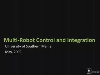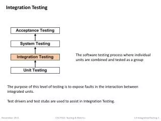
Robot Integration and Testing
This project focuses on the design, integration, and testing of a robot that autonomously cares for plants while navigating urban environments. The team, consisting of members from various engineering disciplines, aimed to combine navigation and locomotion systems, meeting customer specifications for movement and functionality. Despite delays in shell creation and integration challenges with navigation components, the robot successfully demonstrated core functionalities, including wireless communication and sensor data acquisition. Future teams are advised to prioritize testing customer specifications and consider additional functionalities for improved performance.

Robot Integration and Testing
E N D
Presentation Transcript
Robot Integration and Testing Pat Arrigo – Team Lead/ME Wes Coleman – ME Steve Guenther – EE Adam Spirer – EE Vernon Vantucci– CE Aaron Zimmerman - ME
Introduction • Third Team on Project Track • Inherited Project from Locomotion and Navigation Teams • Worked in parallel with Robot Applications Team
Initial Project Expectations and Goals • Fully Integrate Navigation Software/Electrical Components with Locomotion Chassis and Motors/Motor Control • Test Customer Specifications • Integrate Robot with Application Team’s Software • Create and Mount shell to Chassis and Paint
Customer Needs and Specifications • Robot carries and cares for a plant • Robot moves slowly • Promotes innovation and green values at RIT • Friendly to passing pedestrians • Must be able to return home • Last an entire day of roaming • System uses navigation and plant sensors in order to capture real-world data, and gain an understanding of the surroundings. • Develop firmware for all of the sensors. • Develop software to perform navigational tasks using sensor data. • Maintain a wireless connection to a host computer in order to send status updates. P10215 P10216
Shell Creation • Small model used to prove concept • Sculpting full scale took longer than expected • Sheer scale • Material Differences: Styrofoam vs. Pink foam • Despite delays, shell is complete and painted
Major Setbacks • Navigation Team components and Locomotion Motor Controllers did not work properly • Majority of MSD II spent on debugging and fixing • Robot was not fully functional until ~Week 8 • Testing of Specifications was not done due to time constraints (suggested for future teams)
Milestones- MSDII • Week 1 • Initial shell design finalized, components purchased • Week 2 • Evaluation of Locomotion/firmware “bugs” • Week 4 • Header board completion • Week 5 • Sensors remounted • Shell Top & Front complete • Week 6 • New encoder design integrated • H-Bridge functionality solved • Week 7 • Shell components test fit, trimmed • Shell top, front, sides painted • Remote Control implemented via gamepad • Week 8 • Remote Control finalized • Shell top mounted • Plant, solar panels mounted • ImagineRIT • Remote Control verified • Battery charge expectancy verified • Week 9 • Shell front mounts made
Current State of Design • Robot is capable of meeting all locomotion-related requirements • Sensor Data Acquisition • Compass data not being translated correctly • All other positional and plant sensors reporting data correctly • Shell • Shell pieces made • Top & Front trimmed for fit and sensor/plant clearance • Top mounted in final location • Front mounts made, not yet attached to chassis • Rear & sides unmounted, untrimmed • All pieces painted with design scheme • Formal Platform Testing • Originally a project requirement • Platform reconstruction took precedence • Formal test plan methodology developed • No formal test plans run • ImagineRIT platform validation
Suggestions for Future Teams • Test customer specifications (velocity, turning radius etc.) • Powder coat the chassis to prevent rust • Purchase printed circuit board • Integrate Application software with current Robot (to make autonomous) • Add 2 more rear Sonar Sensors • To guard against the back end of Robot bumping into things as it turns
Summary • Number of Original Project Goals Met: 0 • Number of Robots Created: 1 • Senior Design Course: 0 • Senior Design Team: 1