Development of a New Gas-Filled Detection System for Notre Dame's Browne-Buechner Spectrograph
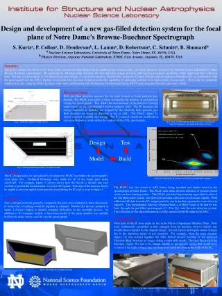
This poster presents the design and development of an innovative gas-filled detection system by the Notre Dame Accelerator Mass Spectrometry (AMS) group, aimed at enhancing the capabilities of the Browne-Buechner spectrograph. The new system comprises a position-sensitive Parallel Grid Avalanche Counter (PGAC) and an Ionization Chamber (IC) to improve measurement precision and data collection speed. This collaborative effort with Argonne National Laboratory enhances particle separation from complex backgrounds, ensuring efficient operations within the Nuclear Science Laboratory.

Development of a New Gas-Filled Detection System for Notre Dame's Browne-Buechner Spectrograph
E N D
Presentation Transcript
Beam tuned to 80MeV 58Ni11+ Fe/Ni Mixed cathode (200:1) injected MANTIS @ 2.9 Torr N2 , B = 0.484T 58Fe Energy Loss (Channel number) 58Ni Position (Channel number) Design and development of a new gas-filled detection system for the focal plane of Notre Dame’s Browne-Buechner Spectrograph S. Kurtza, P. Collona, D. Hendersonb, L. Lamma, D. Robertsona, C. Schmitta, B. Shumardb a Nuclear Science Laboratory, University of Notre Dame, Notre Dame, IN, 46556, USA bPhysics Division, Argonne National Laboratory, 9700S. Cass Avenue, Argonne, IL, 60439, USA Summary This poster outlines the efforts of the Notre Dame Accelerator Mass Spectrometry (AMS) group to create a new, gas-filled, detection system for the Nuclear Science Laboratory’s (NSL) Browne-Buechner spectrograph. By replacing the old photo-plate detectors, the new detection system provides additional measurement capabilities while improving data collection time. The new system consists of two detectors in series (figure 1); a position-sensitive, Parallel Grid Avalanche Counter (PGAC) and an Ionization Chamber (IC). In combination with the spectrograph and the NSL’s Tandem Accelerator, this detection system provides the capability of separating particles from high isobaric backgrounds. This work was primarily conducted on site, using the NSL’s facilities, with some collaboration with the Detector Development Group (DDG) from Argonne National Laboratory (ANL). Detection System Both gas-filled detectors measure the ion pairs formed as beam particles pass through. The PGAC uses grids of wires to measure the position of each particle exiting the spectrograph. This allows the measurement of the particle’s bending radius based on the spectrograph’s known magnetic field. The IC measures the energy deposited as particles are stopped by the relatively high pressure gas. Both detectors are based on detectors in use at ANL. The PGAC (figure 2), simply required assembly and testing. The IC required significant modification (discussed below) to work within the confines of the NSL spectrograph. Fig 1: Schematic Design of PGAC and IC Fig 2: View of PGAC with Back Plate removed, revealing the stack of rectangular wire grids and support circuitry Development Process Design Test Model Build Fig 3: Technical Drawing of the IC’s 4-section Anode 1 - Design The IC design had to be specialized to fit behind the PGAC and within the spectrograph’s focal plane box. Technical Drawings were made for all of the major parts using AutoCAD. For example, figure 3 (above) shows how the Anode is divided into four sections to permit the measurement of several ∆E signals. One side of the detector had to be angled to prevent angled beam particles from hitting the IC wall as seen in figure 1. Fig 6: 2D comparison of position and dE1 for enriched Fe/Ni cathode 4 - Testing The PGAC was first tested at ANL before being installed and further tested in the spectrograph at Notre Dame. The PGAC data alone allowed selection of particles based solely on their bending radius. The PGAC provided functionality equivalent to that of the old photo-plate system, but allowed faster data collection via electronic signals. With additional ∆E data from the IC, unique particles can be further separated as seen above in figure 6. This experimental data was obtained when a 114MeV beam of Ni and Fe was bent, through the gas-filled spectrograph (1.1 Torr N2), into the new detection system. The collection of this data demonstrates a fully operational AMS setup in the NSL. 2 - Model Once a design had been generally completed, the parts were rendered in three dimensions to insure that everything would fit together as planned. Models like the one pictured in figure 4 (below) helped to identify potential difficulties in the assembly process. In addition to 3D computer models, a Styrofoam model of the main chamber was actually built just to make sure it could fit into the spectrograph. 3 - Fabrication Most parts of the IC were made on site in the Physics Department Machine Shop. Parts were continuously assembled as they emerged from the machine shop to identify any modifications required by the original design. Several aspects did require minor changes due to the imperfect nature of real materials. For example, when the main chamber (figure 5a) was welded together, the sides bowed inward resulting in the proposed Electrode-Ring Structure no longer sliding comfortably inside. The final Electrode-Ring Structure (figure 5b) had to be shrunk slightly to prevent the arcing that would have occurred if the high-voltage rings had been positioned too close to the walls of the IC. Fig 4: 3-D Model of complete IC design Fig 5: a) IC main chamber b) IC Electrode Ring Structure attached to back plate