Download
1 / 32
320 likes | 527 Vues
Chapter 5B EGR 270 – Fundamentals of Computer Engineering. 1. X. X/Y. A/Y. B/Y. A. B. Mealy Model. Transition from one state to another depends on the Input, X Output, Y, is specified with the transition Output, Y, depends on both the Present State and the Input, X.

E N D
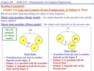
Chapter 5B EGR 270 – Fundamentals of Computer Engineering 1 X X/Y A/Y B/Y A B Mealy Model • Transition from one state to another depends on the Input, X • Output, Y, is specified with the transition • Output, Y, depends on both the Present State and the Input, X Reading Assignment: - Chapter 5 in Logic and Computer Design Fundamentals, 4th Edition by Mano Recall an earlier slide describing two types of state diagrams. Mealy state machine (Mealy model)– the output depends on the present state and the inputs applied. Moore state machine (Moore model)– the output only depends on the present state. We will primarily use Mealy models X X/Y C/Y C Moore Model • Transition from one state to another depends on the Input, X • Output, Y, is specified with the Present State • Output, Y, depends only on the Present State
Chapter 5B EGR 270 – Fundamentals of Computer Engineering 2 Example: Both a Mealy Model and a Moore Model are used below to specify state machines that will detect the occurrence of two 1’s in a row. 0 A/0 Moore Model: Mealy Model: 0/0 A 1 0 0/0 1/0 B/0 State A: Zero 1’s received State B: One 1 received State C: Two 1’s received 0 B 1 1/1 C/1 1 State A: Zero 1’s received State B: One 1 received • Two states (one flip-flop) • Output of 1 indicates that two inputs of 1 occurred in a row. • Output is not associated with a state, but with the transition. • Three states (two flip-flops) • Output of 1 indicates that two inputs of 1 occurred in a row. • Output is associated with state C.
Chapter 5B EGR 270 – Fundamentals of Computer Engineering 3 Comparison of Mealy models and Moore models:
Chapter 5B EGR 270 – Fundamentals of Computer Engineering Sequence Detector: An example of a circuit whose output sequence is critical and the numeric value of the states is unimportant is a “sequence detector”. Such a circuit might be used to detect a certain bit pattern (such as in synchronizing two signals) or for a digital lock – where the lock is unlocked when a correct combination (sequence) is entered. Input, X Sequence Detector Output, Y Example: Detect the sequence 101, including overlapping sequences. Define the output, Y, as follows: Fill out the values for Y in the table below:
Chapter 5B EGR 270 – Fundamentals of Computer Engineering State A Input 0 1 0 1 0 1 1 0 0 1 0 1 0 1 0 0 Output Example: Design a sequence detector to detect the sequence 1010. The sequence detector should also detect overlapping sequences. The circuit should output a binary 1 when a valid sequence is detected. Use a Moore model. One strategy is to use 5 states: A - 0 correct values in sequence B - 1 correct value in sequence C - 2 correct values in sequence D - 3 correct values in sequence E - 4 correct values in sequence Test the state diagram with the input sequence 0101011001010100
Chapter 5B EGR 270 – Fundamentals of Computer Engineering State A Input 0 1 0 1 0 1 1 0 0 1 0 1 0 1 0 0 Output Example: Repeat the previous example using a Mealy model. Note that only 4 states are required. One strategy is to use 4 states: A - 0 correct values in sequence B - 1 correct value in sequence C - 2 correct values in sequence D - 3 correct values in sequence Test the state diagram with the input sequence 0101011001010100 Is the output identical to the output from the previous example?
Chapter 5B EGR 270 – Fundamentals of Computer Engineering • Example: (continued) • How many flip-flops are required using the Moore model? • How many flip-flops are required using the Mealy model? • Complete the excitation table for the Mealy model circuit.
Chapter 5B EGR 270 – Fundamentals of Computer Engineering Example: (continued) Draw the logic diagram. Clearly label the input sequence, x, and the output sequence, y.
Chapter 5B EGR 270 – Fundamentals of Computer Engineering Example: Serial 2’s Complementer Circuit Design a one input, one output serial 2’s complementer using a Mealy Model. The circuit accepts a string of bits from the input and generates the 2’s complement at the output. The circuit can be reset asynchronously to start and stop the operation. Implement the circuit using JK flip-flop(s). Design: Recall that one method for finding a 2’s complement is to start with the LSB and proceed until the first 1 is encountered and then take the 1’s complement of all bits. Input Sequence, x Serial 2’s Complementer 2’s complement of Input Sequence, y complement 1 0 0 1 1 0 0 Input, x: 0 1 1 0 1 0 0 Output, y: State A (output = input) State B (output = 1’s complement of input)
Chapter 5B EGR 270 – Fundamentals of Computer Engineering • Example: (continued) • Draw the state diagram using states A and B as defined on the previous slide
Chapter 5B EGR 270 – Fundamentals of Computer Engineering • Example: (continued) • How many flip-flops are needed for 2 states? • Fill out the excitation table. • Use K-maps to find expressions for J, K, and y
Chapter 5B EGR 270 – Fundamentals of Computer Engineering • Example: (continued) • Draw the logic diagram
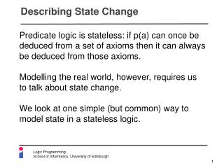
Chapter 5B EGR 270 – Fundamentals of Computer Engineering • Recall that three methods for designing sequential circuits will be covered: • 1) Excitation table method (already covered) • 2) State equation method • 3) “One-Hot” method • Designing Sequential Circuits using State Equations • Before the state equation method is covered, two related topics must be covered: • state equations • flip-flop characteristic equations State Equations A state equation is an equation for the next state of a sequential logic circuit. It has the form: Q(t + 1) = (Boolean expression involving present states and inputs) The state equations are simply formed using the “Next State” shown in the state table.
Chapter 5B EGR 270 – Fundamentals of Computer Engineering 0 1 0 1 0 4 1 0 1 1 2 3 0 1 0 Example: Find the state equations for the state diagram shown below.
Chapter 5B EGR 270 – Fundamentals of Computer Engineering Flip-flop characteristic equations Flip-flop behavior has been expressed so far using truth tables or excitation tables. The next state (output) of a flip-flop can also be described algebraically using a flip-flop state equation or flip-flop characteristic equation. Example: Develop the flip-flop characteristic equation for a JK flip-flop.
Chapter 5B EGR 270 – Fundamentals of Computer Engineering Example:Develop flip-flop characteristic equationsfor SR, D, and T flip-flops.
Chapter 5B EGR 270 – Fundamentals of Computer Engineering Designing Sequential Circuits using State Equations – Procedure 1. Form the state table. 2. Develop the state equations from the state table. 3. Determine the type of flip-flop to be used. 4. Manipulate the state equation into the form of the characteristic equation for each flip-flop. This will yield the flip-flop input expressions. • Notes: • It is easiest to design by state equations using D flip-flops. • Many programmable devices only support D flip-flop designs, so state equations are very useful. • JK flip-flop designs will yield the simplest circuits in general. • Designing circuits by the excitation table method and by the state equation method should yield the same results.
Chapter 5B EGR 270 – Fundamentals of Computer Engineering Example: Design a modulo-7 counter by the state equation methodusing D flip-flops Create the state table
Chapter 5B EGR 270 – Fundamentals of Computer Engineering Example: (continued) Form the state equations Determine the D flip-flop inputs (trivial!)
Chapter 5B EGR 270 – Fundamentals of Computer Engineering Example: (continued) Draw the logic diagram using D flip-flops
Chapter 5B EGR 270 – Fundamentals of Computer Engineering Example: Repeat the last example using JK flip-flops. Create the state table – same as before Form the state equations – same as before Determine the JK flip-flop inputs (much harder than with D flip-flops) State Equation A(t+1) So JA = BC
Chapter 5B EGR 270 – Fundamentals of Computer Engineering Example: (continued) - Repeat for the next two state equations State Equation B(t+1) State Equation C(t+1)
Chapter 5B EGR 270 – Fundamentals of Computer Engineering Example: (continued) Draw the logic diagram using JK flip-flops
Chapter 5B EGR 270 – Fundamentals of Computer Engineering Three methods for designing synchronous sequential circuits: 1) Excitation table method (already covered) 2) State equation method (already covered) “One-Hot” method “One-Hot” Method for designing synchronous sequential circuits The “one-hot” method is based on the idea that N flip-flops will be used to represent N states and that at any given time only one of the states is “hot” or HIGH – the current state.
Chapter 5B EGR 270 – Fundamentals of Computer Engineering Q 0 Q 1 State A is “hot” Other connections and circuitry Other connections and circuitry Q 1 Q 0 State B is “hot” Q 0 Q 0 Q 0 Q 0 Example: A state diagram with 4 states would require 4 flip-flops and the outputs would be as follows: (Similar diagrams for states C and D are not shown.)
Chapter 5B EGR 270 – Fundamentals of Computer Engineering Entry Entry N State 0 Y X = 1? Exit 0 Exit 1 Exit “One-Hot” Method - Advantage The design process is simple for the “one-hot” method. The connections for D flip-flop designs can be seen easily from an ASM (Algorithmic State Machine) Chart, which is similar to a flowchart. Also note that this method can allow for a simple way to describe sequential circuits in VHDL. Algorithmic State Machine (ASM) Chart symbols ASM Charts are covered in more detail in Chapter 8 of the text. For now, we will just introduce two ASM chart symbols (elements). Decision box State box
Chapter 5B EGR 270 – Fundamentals of Computer Engineering “One-Hot” Method - Disadvantage The “one-hot method requires a potentially large number of flip-flops. Since the states are not encoded as with other methods (i.e., one flip-flop is required for each state), designs may require a large number of flip-flops. Examples are provided below to illustrate this problem. Note: When implementing sequential circuits using Aldec Active-HDL , the software gives the user a choice of implementing a “one-hot” design or using encoded states (the default) . Using encoded states saves many flip-flops.
Chapter 5B EGR 270 – Fundamentals of Computer Engineering ASM Chart State diagram State 0 So Q0(t+1) = D0 = Q4 0 State 1 So Q1(t+1) = D1 = Q0 4 1 State 2 So Q2(t+1) = D2 = Q1 State 3 So Q3(t+1) = D3 = Q2 2 3 State 4 So Q4(t+1) = D4 = Q3 Example: Use the “one-hot” method to design a mod-5 counter. Note that each state box essentially acts like a D flip-flop where the entry to the box is D and the exit from the box is Q. State Equations D0 Q0 D1 Q1 D2 Q2 D3 Q3 D4 Q4
Chapter 5B EGR 270 – Fundamentals of Computer Engineering Q0(t+1) = D0 = Q4 Q1(t+1) = D1 = Q0 Q2(t+1) = D2 = Q1 Q3(t+1) = D3 = Q2 Q4(t+1) = D4 = Q3 D0 Q0 D1 D2 Q2 D3 Q3 D4 Q1 Q4 Q0 Q1 Q2 Q3 Q4 CK Example (mod-5 counter continued): State Equations: Logic Diagram: Recall that the outputs above are not encoded. An encoder can be used to create encoded outputs if they are needed (for example, to send the outputs to a BCD-to-7 segment decoder). This is illustrated on the following slide.
Chapter 5B EGR 270 – Fundamentals of Computer Engineering Example (mod-5 counter continued): CK Logic Diagram with encoder added D4 D2 D1 D3 D0 Q0 Q4 Q2 Q1 Q3 0 1 2 3 4 5 6 7 8 x 3 Encoder (MSB) A B C Exercise: Add binary values to the logic diagram if the counter is in state 3 Q2 Q3 Q1 Q0 Q4 0 0 0 A B C D (LSB) BCD-to 7-segment decoder 0
Chapter 5B EGR 270 State 0 Q0(t+1) = D0 = 0 1 x = 0 or 1? State diagram State 1 Q1(t+1) = D1 = 0 1 1 0 1 x = 0 or 1? ASM Chart: 0 4 1 0 State 2 Q2(t+1) = D2 = 0 0 0 1 x = 0 or 1? 1 1 0 2 3 State 3 Q3(t+1) = D3 = 1 0 1 x = 0 or 1? State 4 Q4(t+1) = D4 = 0 1 x = 0 or 1? • Example: Use the “one-hot” method to design a mod-5 counter UP/DOWN. • Let x be an input control where if: • x = 0 the counter counts down • x = 1 the counter counts up • Label D and Q next to each state box • Find the state equations
Chapter 5B EGR 270 – Fundamentals of Computer Engineering Example (mod-5 UP/DOWN counter continued) : Draw the logic diagram