Download
1 / 16
160 likes | 227 Vues
Explore practical problems in VLSI physical design using Elmore Routing Tree (ERT) and Steiner Elmore Routing Tree (SERT) algorithms for delay minimization. Learn about adding edges, delay calculations, and optimizing Elmore delay with real-world examples. Understand the differences between ERT and SERT under different technology parameters.

E N D
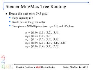
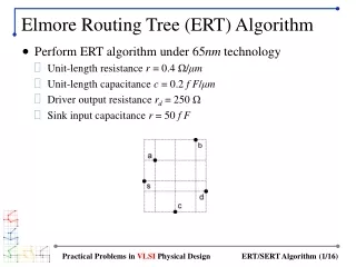
Elmore Routing Tree (ERT) Algorithm • Perform ERT algorithm under 65nm technology • Unit-length resistance r = 0.4 Ω/μm • Unit-length capacitance c = 0.2 f F/μm • Driver output resistance rd = 250 Ω • Sink input capacitance r = 50 f F Practical Problems in VLSI Physical Design
Adding First Edge • Simply add the nearest neighbor to the source • Add (s,a) Practical Problems in VLSI Physical Design
Adding Second Edge • Rule: each node in T can connect to its nearest neighbor • Two edges to consider: (a,b), (s,c) • Elmore delay calculations shown on next slides Practical Problems in VLSI Physical Design
Elmore Delay Calculation • Case 1: edge (a,b) Practical Problems in VLSI Physical Design
Elmore Delay Calculation (cont) • Case 2: edge (s,c) • It is easy to see that t(c) > t(a) • Elmore delay is t(c) = 2035ps • Thus, we add (s,c) to minimize maximum Elmore delay Practical Problems in VLSI Physical Design
Adding Third Edge • Three edges to consider: (a,b), (s,d), (c,d) • Elmore delay: t(b) = 4267.5ps, t(d) = 2937.5ps, t(d) = 5917.5ps • Add (s,d) t(c) = 2937.5ps Practical Problems in VLSI Physical Design
Adding Fourth Edge • Four edges to consider: (a,b), (s,b), (c,b), (d,b) • In all these cases, delay to b is the maximum • t(b) = 4630ps, 4720ps, 10720ps, 8310ps, respectively • Add (a,b) t(b) = 4630ps Practical Problems in VLSI Physical Design
Final ERT Result • Maximum Elmore delay is t(b) = 4630ps • No Steiner node used • Star-shaped topology Practical Problems in VLSI Physical Design
Steiner Elmore Routing Tree (SERT) • Perform SERT algorithm under 1.2μm technology • Unit-length resistance r = 0.073 Ω/μm • Unit-length capacitance c = 0.083 f F/μm • Driver output resistance rd = 212 Ω • Sink input capacitance r = 7.1 f F Practical Problems in VLSI Physical Design
First Iteration • Simply add the nearest neighbor to the source • Add (s,a) Practical Problems in VLSI Physical Design
Second Iteration • Rule: each node not in T can connect to each edge in T using a Steiner point or directly to source • 6 edges to consider: (a,b), (s,b), (p,d), (s,d), (p,c), (s,c) • Node p is a Steiner node Practical Problems in VLSI Physical Design
Second Iteration (cont) • Case (e) results in minimum delay: t(c) = 268.6ps • Add (p,c) t(c) = 268.6ps Practical Problems in VLSI Physical Design
Third Iteration • 7 edges to consider t(d) = 413.3ps Practical Problems in VLSI Physical Design
Fourth Iteration • 6 edges to consider t(b) = 606.3ps t(d) = 557.3ps Practical Problems in VLSI Physical Design
Final SERT Result • Maximum Elmore delay is t(b) = 606.3ps • Two Steiner nodes used Practical Problems in VLSI Physical Design
ERT vs SERT • Not a fair comparison • Technology parameters are different (65nm vs 1.8μm) t(b) = 606.3ps t(b) = 4630ps Practical Problems in VLSI Physical Design