Precision Girdle Design for Plasma Shutter Clearance Optimization
Enhance plasma shutter efficiency and functionality with an innovative girdle design for precise clearance optimization.

Precision Girdle Design for Plasma Shutter Clearance Optimization
E N D
Presentation Transcript
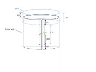
girdle 0.50 1.00 0.50 Shutter body 0.50 2.051 1.025 0.50
0.065 3.61 0.12 0.125 girdle (new In 2002) 1.00 3.10 0.50 3.11 interference is about 0.015 OD = 3.75 0.06 3.37+2 * 0.12 = 3.61 vs 3.625 shutter bottom lip (new in 2002) 0.062 3.37 0.18 0.12? 0.20
Dimensions Blue: directly from E-MIT-46 + E-MIT052 green: inferred from difference and/or photo red: uncertain. Need to verify with more photos 0.065 3.61 Proposal: position shutter off-center with respect to turret (using Vespel bushing) to provide additional clearance at L1 ‘snout’ 0.12 0.125 (guess / photo) girdle (new In 2002) 1.00 (photo) 3.10 0.50 (photo) 3.11 shutter 3.051 OD = 3.75 3.37+2*0.12 = 3.61 vs ID=3.63. So nominal clearance between button and shutter is 0.010”. ID = 3.63 0.06 (difference) clearance = 0.13 (difference) snout for L1 lens holder sticks out maybe 0.12-0.14 interference 0.10 – 0.12 (photo) 0.06 (photo + difference) 3.37 bottom lip (new in 2002) 0.18 0.128 (difference) 0.16-0.18 (photo / difference) Need to check this) 3.625
turret girdle L-1 lens to plasma shutter ‘elbow’ Is there value in adding a vertical ‘lip’ to ensure that shutter can’t be pulled away from the turret? Vespel SP-3 “L”-bushing
turret girdle L-1 lens to plasma shutter ‘elbow’ Vespel SP-3 “L”-bushing
Offset joint at two halves of shutter From joint of Vespel bushings T-clip Vespel bushing Vespel bushing Shutter body (right half) Shutter body (left half) turret