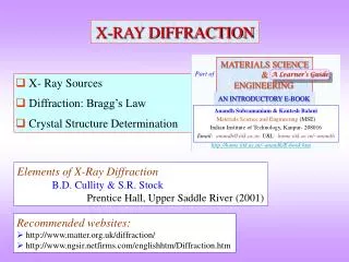
CHAPTER 3 X-RAY DIFFRACTION IN CRYSTAL
CHAPTER 3 X-RAY DIFFRACTION IN CRYSTAL. X-Ray Diffraction Diffraction of Waves by Crystals X-Ray Diffraction Bragg Equation X-Ray Methods Neutron & Electron Diffraction. Bertha Röntgen’s Hand 8 Nov, 1895. X-RAY.

CHAPTER 3 X-RAY DIFFRACTION IN CRYSTAL
E N D
Presentation Transcript
CHAPTER 3X-RAY DIFFRACTION IN CRYSTAL X-Ray Diffraction Diffraction of Waves by Crystals X-Ray Diffraction Bragg Equation X-Ray Methods Neutron & Electron Diffraction Bertha Röntgen’s Hand 8 Nov, 1895
X-RAY • X-rays were discovered in 1895 by the German physicist Wilhelm Conrad Röntgen and were so named because their nature was unknown at the time. • He was awarded the Nobel prize for physics in 1901. Wilhelm Conrad Röntgen (1845-1923)
X-RAY PROPERTIES • X ray, invisible, highly penetrating electromagnetic radiation of much shorter wavelength (higher frequency) than visible light. The wavelength range for X rays is from about 10-8 m to about 10-11 m, the corresponding frequency range is from about 3 × 10¹⁶ Hz to about 3 × 10¹⁹ Hz.
X-RAY ENERGY • Electromagnetic radiation described as having packets of energy, or photons. The energy of the photon is related to its frequency by the following formula: =Wavelength , ע = Frequency , c = Velocity of light x-ray≈ 10-10 ≈1A° E ~ 104 ev
PRODUCTION OF X-RAYS • Visible light photons and X-ray photons are both produced by the movement of electrons in atoms. Electrons occupy different energy levels, or orbitals, around an atom's nucleus. • When an electron drops to a lower orbital, it needs to release some energy; it releases the extra energy in the form of a photon. The energy level of the photon depends on how far the electron dropped between orbitals.
X-RAY TUBE • X rays can be produced in a highly evacuated glass bulb, called an X-ray tube, that contains essentially two electrodes—an anode made of platinum, tungsten, or another heavy metal of high melting point, and a cathode. When a high voltage is applied between the electrodes, streams of electrons (cathode rays) are accelerated from the cathode to the anode and produce X rays as they strike the anode. Evacuated glass bulb Cathode Anode
Monochromatic and Broad Spectrum of X-rays • X-rays can be created by bombarding a metal target with high energy (> ) electrons. • Some of these electrons excite electrons from core states in the metal, which then recombine, producing highly monochromatic X-rays. These are referred to as characteristic X-ray lines. • Other electrons, which are decelerated by the periodic potential of the metal, produce a broad spectrum of X-ray frequencies. • Depending on the diffraction experiment, either or both of these X-ray spectra can be used.
ABSORPTION OF X-RAYS • The atoms that make up your body tissue absorb visible light photons very well. The energy level of the photon fits with various energy differences between electron positions. • Radio waves don't have enough energy to move electrons between orbitals in larger atoms, so they pass through most stuff. X-ray photons also pass through most things, but for the opposite reason: They have too much energy. ...something you won't see very often (Visible Light) X-ray
Generation of X-rays (K-Shell Knockout) An electron in a higher orbital immediately falls to the lower energy level, releasing its extra energy in the form of a photon. It's a big drop, so the photon has a high energy level; it is an X-ray photon. The free electron collides with the tungsten atom,knocking an electron out of a lower orbital. A higher orbital electron fills the emptyposition, releasing its excess energy as a photon.
Absorption of X-rays • A larger atom is more likely to absorb an X-ray photon in this way, because larger atoms have greater energy differences between orbitals -- the energy level more closely matches the energy of the photon. Smaller atoms, where the electron orbitals are separated by relatively low jumps in energy, are less likely to absorb X-ray photons. • The soft tissue in your body is composed of smaller atoms, and so does not absorb X-ray photons particularly well. The calcium atoms that make up your bones are much larger, so they are better at absorbing X-ray photons.
DIFFRACTION • Diffraction is a wave phenomenon in which the apparent bending and spreading of waves when they meet an obstruction. • Diffraction occurs withelectromagnetic waves, such as light and radio waves, and also in sound waves and water waves. • The most conceptually simple example of diffraction is double-slit diffraction, that’s why firstly we remember light diffraction. Width b Variable (500-1500 nm) Wavelength Constant (600 nm) Distance d = Constant
LIGHT DIFFRACTION • Light diffraction is caused by light bending around the edge of an object. The interference pattern of bright and dark lines from the diffraction experiment can only be explained by the additive nature of waves; wave peaks can add together to make a brighter light, or a peak and a through will cancel each other out and result in darkness. Thus Young’s light interference experiment proves that light has wavelike properties.
Constructive interference is the result of synchronized light waves that add together to increase the light intensity. Destructive İnterference . results when two out-of-phase light waves cancel each other out, resulting in darkness. Constructive & Destructive Waves
Single particle To understand diffraction we also have to consider what happens when a wave interacts with a single particle.The particle scatters the incident beam uniformly in all directions Solid material What happens if the beam is incident on solid material? If we consider a crystalline material, the scattered beams may add together in a few directions and reinforce each other to give diffracted beams Diffraction from a particle and solid
Diffraction of Waves by Crystals A crystal is a periodic structure ( unit cells are repeated regularly) Solid State Physics deals how the waves are propagated through such periodic structures. In this chapter we study the crystal structure through the diffraction of photons (X-ray), nuetrons and electrons. The general princibles will be the same for each type of waves.
Diffraction of Waves by Crystals • The diffraction depends on the crystal structure and on the wavelength. • At optical wavelengths such as 5000 angstroms the superposition of the waves scattered elastically by the individual atoms of a crystal results in ordinary optical refraction. • When the wavelength of the radiation is comparable with or smaller than the lattice constant, one can find diffracted beams in directions quite different from the incident radiation.
Diffraction of Waves by Crystals • The structure of a crystal can be determined by studying the diffraction pattern of a beam of radiation incident on the crystal. • Beam diffraction takes place only in certain specific directions, much as light is diffracted by a grating. • By measuring the directions of the diffraction and the corresponding intensities, one obtains information concerning the crystal structure responsible for diffraction.
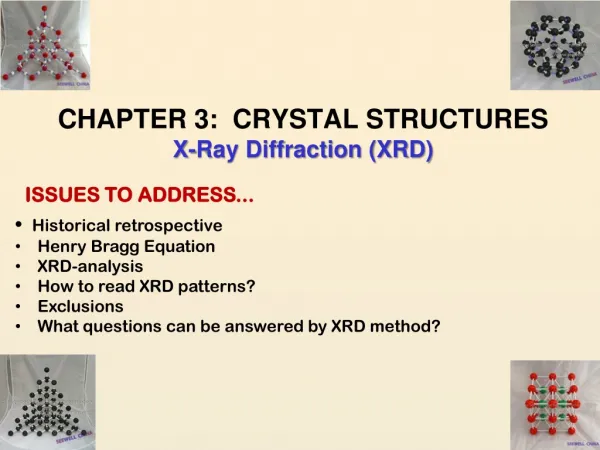
X-RAY CRYSTALLOGRAPHY • X-ray crystallography is a technique in crystallography in which the pattern produced by the diffraction of x-rays through the closely spaced lattice of atoms in a crystal is recorded and then analyzed to reveal the nature of that lattice. • X-ray diffraction = (XRD)
X-Ray Crystallography • The wavelength of X-rays is typically 1 A°, comparable to the interatomic spacing (distances between atoms or ions) in solids. • We need X-rays:
Crystal Structure Determination A crystal behaves as a 3-D diffraction grating for x-rays • In a diffraction experiment, the spacing of lines on the grating can be deduced from the separation of the diffraction maximaInformation about the structure of the lines on the grating can be obtained by measuring the relative intensities of different orders • Similarly, measurement of the separation of the X-ray diffraction maxima from a crystal allows us to determine the size of the unit cell and from the intensities of diffracted beams one can obtain information about the arrangement of atoms within the cell.
X-Ray Diffraction W. L. Bragg presented a simple explanation of the diffracted beams from a crystal. The Bragg derivation is simple but is convincing only since it reproduces the correct result.
X-Ray Diffraction & Bragg Equation • English physicists Sir W.H. Bragg and his son Sir W.L. Braggdeveloped a relationship in 1913 to explain why the cleavagefaces of crystals appear to reflect X-ray beams at certainangles ofincidence (theta, θ).This observation is anexample of X-ray wave interference. Sir William Henry Bragg (1862-1942), William Lawrence Bragg (1890-1971) • 1915, the father and son were awarded the Nobel prize for physics "for their services in the analysis of crystal structure by means of Xrays".
Bragg Equation • Bragg law identifies the angles of the incident radiation relative to the lattice planes for which diffraction peaks occurs. • Bragg derived the condition for constructive interference of the X-rays scattered from a set of parallel lattice planes.
BRAGG EQUATION • W.L. Bragg considered crystals to bemadeup of parallel planes of atoms. Incident waves are reflected specularly from parallel planes of atoms in the crystal, with each plane is reflecting only a very small fraction of the radiation, like a lightly silvered mirror. • In mirrorlike reflection the angle of incidence is equal to the angle of reflection. ө ө
Diffraction Condition • The diffracted beams are foundto occur when the reflections from planes of atoms interfereconstructively. • We treat elastic scattering, in which the energy of X-ray is not changed on reflection.
Bragg Equation • When the X-rays strike a layer of a crystal, some of them will be reflected. We are interested in X-rays that are in-phase with one another. X-rays that add together constructively in x-ray diffraction analysis in-phase before they are reflected and after they reflected. Incident angle Reflected angle Wavelength of X-ray Total Diffracted Angle
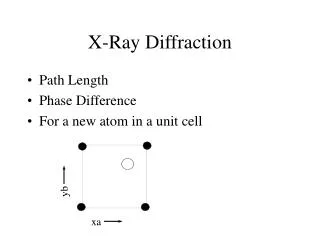
Bragg Equation These two x-ray beams travel slightly different distances. The difference in the distances traveled is related to the distance between the adjacent layers. Connecting the two beams with perpendicular lines shows the difference between the top and the bottom beams. The line CE is equivalent to the distance between the two layers (d)
Bragg Law • The length DE is the same as EF, so the total distance traveled by the bottom wave is expressed by: • Constructive interference of the radiation from successive planes occurs when the path difference is an integral number of wavelenghts. This is the Bragg Law.
Bragg Equation where, d is the spacing of the planes and n is the order of diffraction. • Bragg reflection can only occur for wavelength • This is why we cannot use visible light. No diffraction occurs when the above condition is not satisfied. • The diffracted beams (reflections) from any set of lattice planes can only occur at particular angles pradicted by the Bragg law.
Scattering of X-rays from adjacent lattice points A and B X-rays are incident at an angle on one of the planes of the set. There will be constructive interference of the waves scattered from the two successive lattice points A and B in the plane if the distances AC and DB are equal.
Constructive interference of waves scattered from the same plane If the scattered wave makes the same angle to the plane as the incident wave The diffracted wave looks as if it has been reflected from the plane We consider the scattering from lattice points rather than atoms because it is the basis of atoms associated with each lattice point that is the true repeat unit of the crystal; The lattice point is analoque of the line on optical diffraction grating and the basis representsthe structure of the line.
Diffraction maximum Coherent scattering from a single plane is not sufficient to obtain a diffraction maximum. It is also necessary that successive planes should scatter in phase • This will be the case if the path difference for scattering off two adjacent planes is an integral number of wavelengths
Labelling the reflection planes • To label the reflections, Miller indices of the planes can be used. • A beam corresponding to a value of n>1 could be identified by a statement such as ‘the nth-order reflections from the (hkl) planes’. • (nh nk nl) reflection Third-order reflection from (111) plane (333) reflection
n-th order diffraction off (hkl) planes • Rewriting the Bragg law which makes n-th order diffraction off (hkl) planes of spacing ‘d’ look like first-order diffraction off planes of spacing d/n. • Planes of this reduced spacing would have Miller indices (nh nk nl).
X-ray structure analysis of NaCl and KCl The GENERAL PRINCIBLES of X-RAY STRUCTURE ANALYSIS to DEDUCE the STRUCTURE of NaCl and KCl Bragg used an ordinary spectrometer and measured the intensity of specular reflection from a cleaved face of a crystal found six values of for which a sharp peak in intensity occurred, corresponding to three characteristics wavelengths (K,L and M x-rays) in first and second order (n=1 and n=2 in Bragg law) • By repeating the experiment with a different crystal face he could use his eqn. to find for example the ratio of (100) and (111) plane spacings, information that confirmed the cubic symmetry of the atomic arrangement.
Details of structure Details of structure were than deduced from the differences between the diffraction patterns for NaCl and KCl. • Major difference; absence of (111) reflection in KCl compared to a weak but detectable (111) reflection in NaCl. • This arises because the K and Cl ions both have the argon electron shell structure and hence scatter x-rays almost equally whereas Na and Cl ions have different scattering strengths. (111) reflection in NaCl corresponds to one wavelength of path difference between neighbouring (111) planes.
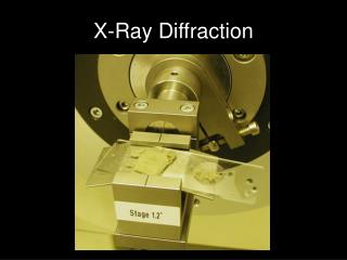
Experimental arrangements for x-ray diffraction • Since the pioneering work of Bragg, x-ray diffraction has become into a routine technique for the determination of crsytal structure.
Bragg Equation Since Bragg's Law applies to all sets of crystal planes, the lattice can be deduced from the diffraction pattern,makinguse of general expressions for the spacing of theplanesin terms of their Miller indices. For cubic structures Note that the smaller the spacing the higher the angle of diffraction, i.e. the spacing of peaks in the diffraction pattern is inversely proportional to the spacing of the planes in the lattice. The diffraction pattern will reflect the symmetry properties of the lattice.
Bragg Equation A simple example is the difference between the series of (n00) reflections for a simple cubic and a body centred cubic lattice. For the simple cubic lattice, all values of n will give Bragg peaks. However, for the body centred cubic lattice the (100) planes are interleaved by an equivalent set at the halfway position. At the angle where Bragg's Law would give the (100) reflection the interleaved planes will give a reflection exactly out of phase with that from the primary planes, which will exactly cancel the signal. There is no signal from (n00) planes with odd values of n. This kind of argument leads to rules for identifying the lattice symmetry from "missing" reflections, which are often quite simple.
Types of X-ray camera There are many types of X-ray camera to sort out reflections from different crystal planes. We will study only three types of X-ray photograph that are widely used for the simple structures. • Laue photograph • Rotating crystal method • Powder photograph
LAUE METHOD • The Laue method is mainly used to determine the orientation of large single crystals while radiation is reflected from, or transmitted through a fixed crystal. • The diffracted beams form arrays of spots, that lie on curves on the film. • The Bragg angle is fixed for every set of planes in the crystal. Each set of planes picks out and diffracts the particular wavelength from the white radiation that satisfies the Bragg lawfor the values of d and θ involved.
Back-reflection Laue Method • In the back-reflection method, the film is placed between the x-ray source and the crystal. The beams which are diffracted in a backward direction are recorded. • One side of the cone of Laue reflections is defined by the transmitted beam. The film intersects the cone, with the diffraction spots generally lying on an hyperbola. Single Crystal Film X-Ray
Transmission Laue Method • In the transmission Laue method, the film is placed behind the crystal to record beams which are transmitted through the crystal. • One side of the cone of Laue reflections is defined by the transmitted beam. The film intersects the cone, with the diffraction spots generally lying on an ellipse. Single Crystal Film X-Ray
Laue Pattern • The symmetry of the spot pattern reflects the symmetry of the crystal when viewed along the direction of the incident beam. Laue method is often used to determine the orientation of single crystals by means of illuminating the crystal with a continuos spectrum of X-rays; • Single crystal • Continous spectrum of x-rays • Symmetry of the crystal; orientation
Crystal structure determination by Laue method • Therefore, the Laue method is mainly used to determine the crystal orientation. • Although the Laue method can also be used to determine the crystal structure, several wavelengths can reflect in different orders from the same set of planes, with the different order reflections superimposed on the same spot in the film. This makes crystal structure determination by spot intensity diffucult. • Rotating crystal method overcomes this problem. How?
ROTATING CRYSTAL METHOD • In the rotating crystal method, a single crystal is mounted with an axis normal to a monochromatic x-ray beam. A cylindrical film is placed around it and the crystal is rotated about the chosen axis. • As the crystal rotates, sets of lattice planes will at some point make the correct Bragg angle for the monochromatic incident beam,and at that point a diffracted beam will be formed.