Texas Instruments Incorporated
500 likes | 523 Vues
Explore the detailed block diagram and operational functionality of the TMS320F2812 digital signal controller, including PWM circuits, output logic, and GP timers. Learn about various events and control registers for efficient usage.

Texas Instruments Incorporated
E N D
Presentation Transcript
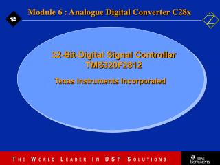
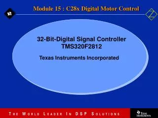
Module 5 : Event Manager C28x 32-Bit-Digital Signal Controller TMS320F2812 Texas Instruments Incorporated
Event Manager Block Diagram (EVA) PWM Circuits Output Logic PWM Circuits Output Logic PWM Circuits Output Logic GP Timer 2 Compare Compare Unit 1 GP Timer 1 Compare GP Timer 2 Compare Unit 2 GP Timer 1 QEP Circuit Compare Unit 3 MUX Reset PIE 2 / TCLKINA / TDIRA EV Control Registers / Logic ADC Start Output Logic T1PWM_T1CMP • PWM1 PWM2 PWM3 Data Bus PWM4 PWM5 PWM6 Output Logic T2PWM_T2CMP CLK DIR • CAP1/QEP1 Capture Units • CAP2/QEP2 • CAP3/QEPI1
General-Purpose Timers (EVA) PWM Circuits Output Logic PWM Circuits Output Logic PWM Circuits Output Logic GP Timer 2 Compare Compare Unit 1 GP Timer 1 Compare GP Timer 2 Compare Unit 2 GP Timer 1 QEP Circuit Compare Unit 3 MUX Reset PIE 2 / TCLKINA / TDIRA EV Control Registers / Logic ADC Start Output Logic T1PWM_T1CMP • PWM1 PWM2 PWM3 Data Bus PWM4 PWM5 PWM6 Output Logic T2PWM_T2CMP CLK DIR • CAP1/QEP1 Capture Units • CAP2/QEP2 • CAP3/QEPI1
General-Purpose Timer Block Diagram (EVA) TCLKS 1-0 M U X TxCON . 5 - 4 Shadowed Compare Register Clock Prescaler Compare Logic TPS 2-0 TxCON . 10 - 8 Period Register Shadowed Internal (HSPCLK) TxCMPR . 15 - 0 TxCNT . 15 - 0 GPTCONA TxPWM_ TxCMP Output Logic 16 - Bit Timer Counter External QEP Note: x = 1 or 2 TxPR . 15 - 0
Continuous-Up Counting Mode • Seamless counting continues • Up count period is TxPR+1 (Used for Asymmetric PWM Waveforms) This example: TxCON.3-2 = 00 (reload TxCMPR on underflow) TxPR = 3 TxCMPR = 1 (initially) Prescale = 1 CPU writes a 2 to compare reg. buffer anytime here TxCMPR=2 is loaded here 3 3 3 2 2 2 1 1 1 0 0 0 0 TxCNT Reg. TxPWM/TxCMP (active high) CPUCLK
Continuous-Up/Down Counting Mode • Seamless up/down repetition • Up/down count period is 2*TxPR (Used for Symmetric PWM Waveforms) This example: TxCON.3-2 = 01 (reload TxCMPR on underflow or period match) TxPR = 3 TxCMPR = 1 (initially) Prescale = 1 TxCMPR loads with a 1 TxCMPR loads with a 2 TxCMPR loads with a 1 3 3 2 2 2 2 1 1 1 1 0 0 0 TxCNT Reg. TxPWM/TxCMP (active high) CPUCLK
Generated Outputs and Interrupts PWM period #2 New Period is Auto-loaded on Underflow here CPU Changes Period Reg. Buffer anytime here PWM period #1 Timer Counter Value Comp2 Comp1 TxCMP/TxPWM (active high) TxCMP/TxPWM (active low) Compare Ints Period Ints Underflow Ints
GP Timer Registers Register Address Description GPTCONA 0x007400 General Purpose Timer Control Register A T1CNT 0x007401 Timer 1 Counter Register T1CMPR 0x007402 Timer 1 Compare Register Buffer T1PR 0x007403 Timer 1 Period Register Buffer T1CON 0x007404 Timer 1 Control Register T2CNT 0x007405 Timer 2 Counter Register T2CMPR 0x007406 Timer 2 Compare Register Buffer T2PR 0x007407 Timer 2 Period Register Buffer T2CON 0x007408 Timer 2 Control Register GPTCONB 0x007500 General Purpose Timer Control Register B T3CNT 0x007501 Timer 3 Counter Register T3CMPR 0x007502 Timer 3 Compare Register Buffer T3PR 0x007503 Timer 3 Period Register Buffer T3CON 0x007504 Timer 3 Control Register T4CNT 0x007505 Timer 4 Counter Register T4CMPR 0x007506 Timer 4 Compare Register Buffer T4PR 0x007507 Timer 4 Period Register Buffer T4CON 0x007508 Timer 4 Control Register EVA EVB EXTCONA 0x007409 / EXTCONB 0x007509 ;Extension Control Register
GP Timer Control Register A (EVA)GPTCONA @ 0x007400 Upper Byte: Timer 2 Compare Trip Enable T2CTRIPE(if EXTCONA[0]=1) 0 = disable 1 = enable Timer 1 Compare Trip Enable T1CTRIPE(if EXTCONA[0]=1) 0 = disable 1 = enable 15 14 13 12 11 10-9 8-7 T2STAT T1STAT T2TOADC T1TOADC reserved RESERVED RESERVED GP Timer Status (read-only) 0 = counting down 1 = counting up ADC start by event of GP Timer x 00: no event starts ADC 01: setting of underflow interrupt flag 10: setting of period interrupt flag 11: setting of compare interrupt
GP Timer Control Register A (EVA)GPTCONA @ 0x007400 Lower Byte: Timer 2 Compare Output Enable T2CMPOE(if EXTCONA[0]=1) 0 = disable (hi-Z) 1 = enable Timer 1 Compare Output Enable T1CMPOE(if EXTCONA[0]=1) 0 = disable (hi-Z) 1 = enable 6 5 4 3-2 1-0 TCOMPOE T2PIN T1PIN RESERVED RESERVED TxPWM/TxCMP Output Pin Conditioning 00: forced low 01: active low 10: active high 11: forced high Compare Output Enable (reserved when EXTCONA[0]=1) 0 = all disable (hi-impedance) 1 = all enable
Timer Control Register (EVA)T1CON @ 0x007404 / T2CON @ 0x007408 Count Mode Select 00 = stop/hold 01 = continuous-up/down 10 = continuous-up 11 = directional-up/down Upper Byte: 15 14 13 12 11 10 9 8 reserved FREE SOFT TMODE1 TMODE0 TPS2 TPS1 TPS0 Timer Clock Prescale 000: 1 100: 16 001: 2 101: 32 010: 4 110: 64 011: 8 111: 128 Emulation Halt Behavior 00 = stop immediately 01 = stop at end of period 1x = free run (do not stop)
Timer Control Register (EVA)T1CON @ 0x007404 / T2CON @ 0x007408 Timer Compare Operation Enable 0 = disable 1 = enable Lower Byte: Timer Clock Source 00 = internal (HSPCLK) 01 = external TCLKIN pin 10 = reserved 11 = QEP Period Register Select 0 = use own per. reg. 1 = use Timer 1 per. reg (bit reserved in T1CON) Timer Enable 0 = timer disable 1 = timer enable 7 6 5 4 3 2 1 0 T2SWT1 TENABLE TCLKS1 TCLKS0 TCLD1 TCLD0 TECMPR SELT1PR Start with Timer 1 0 = use own TENABLE 1 = use Timer 1 TENABLE (bit reserved in T1CON) Compare Register Reload Condition 00 = when counter equals zero (underflow) 01 = when counter equals zero or period reg 10 = immediately 11 = reserved
Extension Control Register A (EVA)EXTCONA @ 0x007409 EVSOCE reserved QEPIQUAL QEPIE Independent Compare Output Enable Mode 0 = disable 1 = enable QEP Index Enable 0 = disable 1 = enable 15-4 3 2 1 0 INDCOE EV Start-of-Conversion Output Enable 0 = disable 1 = enable CAP3/QEPI Index Qualification Mode 0 = off 1 = on
GP Timer Compare PWM Exercise • Symmetric PWM is to be generated as follows: • 50 kHz carrier frequency • Timer counter clocked by 30 MHz external clock • PLL multiply by 10/2 • HSPCLK : divide by 2 • Use the 1 prescale option • 25% duty cycle initially • Use GP Timer Compare 1 with PWM output active high • T2PWM/T2CMP pins forced low Determine the initialization values needed in the GPTCONA, T1CON, T1PR, and T1CMPR registers
GP Timer Compare PWM Exercise Solution GPTCONA = (xxx0000001000010)b = 0x0042 T1CON = (xx00100001000010)b = 0x0842 all x’s assigned a value of 0 20 s 1 1 carrier period . . T1PR = = = 750 2 2 13.34 ns timer period T1CMPR = (100% - duty cycle)*T1PR = 0.75*750 = 563 PLLCR = 0x0A HISPCP = 1
EVAIMRA Register @ 0x742C 15 14 13 12 11 10 9 8 - - - - - T1OFINT T1UFINT T1CINT 7 6 5 4 3 2 1 0 T1PINT - - - CMP3INT CMP2INT CMP1INT PDPINT Interrupt Mask Bits 0 = disable interrupt 1 = enable interrupt Bit Event 10: Timer 1 Overflow 9: Timer 1 Underflow 8: Timer 1 Compare match 7: Timer 1 Period match 3: Compare Unit 3, Compare match 2: Compare Unit 2, Compare match 1: Compare Unit 1, Compare match 0: Power Drive Protect input, EVA
EVAIMRB Register @ 0x742D 15 14 13 12 11 10 9 8 - - - - - - - - 7 6 5 4 3 2 1 0 - - - - T2OFINT T2UFINT T2CINT T2PINT Interrupt Mask Bits 0 = disable interrupt 1 = enable interrupt Bit Event 3: Timer 2 Overflow 2: Timer 2 Underflow 1: Timer 2 Compare match 0: Timer 2 Period match
EVAIMRC Register @ 0x742E 15 14 13 12 11 10 9 8 - - - - - - - - 7 6 5 4 3 2 1 0 - - - - - CAP3INT CAP2INT CAP1INT Interrupt Mask Bits 0 = disable interrupt 1 = enable interrupt Bit Event 2: Capture Unit 3 input 1: Capture Unit 2 input 0: Capture Unit 1 input
EVAIFRx Register 15 14 13 12 11 10 9 8 EVAIFRA @0x742F - - - - - T1OFINT T1UFINT T1CINT 7 6 5 4 3 2 1 0 Read: 0 = no event 1 = flag set T1PINT - - - CMP3INT CMP2INT CMP1INT PDPINT 15 14 13 12 11 10 9 8 EVAIFRB @0x7430 - - - - - - - - 7 6 5 4 3 2 1 0 Write: 0 = no effect 1 = reset flag - - - - T2OFINT T2UFINT T2CINT T2PINT 15 14 13 12 11 10 9 8 EVAIFRA @0x7431 - - - - - - - - 7 6 5 4 3 2 1 0 - - - - - CAP3INT CAP2INT CAP1INT
Lab 5: Let’s play a tune ! Aim: • Exercise with Event Manager A General Purpose Timer 1 • Use Lab 4 as a starting point. In Lab 4 we initialised Core Timer 0 to request an interrupt every 50 ms. We can use this ISR to load the next note to T1PWM. • Timer1 output ‘T1PWM’ is connected to a loudspeaker Basic Tune Frequencies: c1 : 264 Hz d : 297 Hz e : 330 Hz f : 352 Hz g : 396 Hz a : 440 Hz h : 495 Hz c2 : 528 Hz
New Registers involved in Lab 5: • General Purpose Timer Control A : GPTCONA • Timer 1 Control Register : T1CON • Timer 1 Period Register : T1PR • Timer 1 Compare Register : T1CMPR • Timer 1 Counter Register : T1CNT • EV- Manager A Interrupt Flag A : EVAIFRA • EV- Manager A Interrupt Flag B : EVAIFRB • EV-Manager A Interrupt Flag C : EVAIFRC • EV- Manager A Interrupt Mask A : EVAIMRA • EV- Manager A Interrupt Mask B : EVAIMRB • EV- Manager A Interrupt Mask C : EVAIMRC • Interrupt Flag Register : IFR • Interrupt Enable Register : IER
Compare Units (EVA) GP Timer 2 Compare Compare Unit 1 GP Timer 2 Compare Unit 2 QEP Circuit Compare Unit 3 MUX Reset PIE 2 / TCLKINA / TDIRA EV Control Registers / Logic ADC Start Output Logic GP Timer 1 Compare T1PWM_T1CMP GP Timer 1 • PWM1 PWM Circuits Output Logic PWM2 PWM3 PWM Circuits Output Logic Data Bus PWM4 PWM5 PWM Circuits Output Logic PWM6 Output Logic T2PWM_T2CMP CLK DIR • CAP1/QEP1 Capture Units • CAP2/QEP2 • CAP3/QEPI1
What is Pulse Width Modulation? • PWM is a scheme to represent a signal as a sequence of pulses • fixed carrier frequency • fixed pulse amplitude • pulse width proportional to instantaneous signal amplitude • PWM energy original signal energy • Differs from PAM (Pulse Amplitude Modulation) • fixed width, variable amplitude
PWM Signal Representation t Original Signal t t T T PWM representation PAM representation same areas (energy)
Why Use PWM in Digital Motor Control? • Desired motor phase currents or voltages are known • Power switching devices are transistors • Difficult to control in proportional region • Easy to control in saturated region • PWM is a digital signal easy for DSP to output DC Supply DC Supply ? PWM Desired signal to motor phase PWM approx. of desired signal Unknown Gate Signal Gate Signal Known with PWM
Asymmetric PWM Waveform TPWM Period Compare Counter Tpwm / Tcmp Pin (active high) Caused by Period match (toggle output in Asym mode only) Caused by Compare match
Symmetric PWM Waveform General Purpose Timer Full Compare Units PWM1 Compare Compare Compare Period Compare Counter PWM2 PWM3 TPWM/TCMP Pin PWM4 PWM5 PWM6 TPWM Period Compare Counter TPWM /TCMP Pin (active high) Interrupts
Voltage source inverter components Upper & lower devices can not be turned on simultaneously (dead band) PWM signal is applied between gate and source + DC bus capacitor - Three phase outputs which go to the motor terminals Power Switching Devices
Compare Units Block Diagram (EVA) Compare Logic CMPRx . 15 - 0 ACTRA . 11 - 0 Shadowed T1CNT . 15 - 0 Compare Action Control Register GP Timer 1 Counter DBTCONA . 11 - 2 Output Logic Dead Band Units PWMy, y+1 COMCONA . 9 FCOMPOE Compare Register Shadowed Note: x = 1, 2, 3; y = 1, 3, 5
Compare Unit Registers Register Address Description COMCONA 0x007411 Compare Control Register A ACTRA 0x007413 Compare Action Control Register A DBTCONA 0x007415 Dead-Band Timer Control Register A CMPR1 0x007417 Compare Register 1 CMPR2 0x007418 Compare Register 2 CMPR3 0x007419 Compare Register 3 EVA COMCONB 0x007511 Compare Control Register B ACTRB 0x007513 Compare Action Control Register B DBTCONB 0x007515 Dead-Band Timer Control Register B CMPR4 0x007517 Compare Register 4 CMPR5 0x007518 Compare Register 5 CMPR6 0x007519 Compare Register 6 EVB EXTCONA 0x007409 / EXTCONB 0x007509 ;Extension Control Register
Compare Control Register (EVA)COMCONA @ 0x007411 Upper Byte: Compare Enable 0 = disable 1 = enable Full Compare Output Enable (reserved when EXTCONA[0]=1) 0 = all disable (hi-impedance) 1 = all enable Space Vector PWM 0 = SV disable 1 = SV enable 15 14 13 12 11 10 9 8 CENABLE CLD1 CLD0 SVENABLE ACTRLD1 ACTRLD0 FCOMPOE PDPINTA PDPINT Status 0 = low 1 = high CMPRx reload condition 00 = when T1CNT = 0 01 = when T1CNT = 0 or T1PR 10 = immediately 11 = reserved ACTRA reload condition 00 = when T1CNT = 0 01 = when T1CNT = 0 or T1PR 10 = immediately 11 = reserved
Compare Control Register (EVA)COMCONA @ 0x007411 RESERVED RESERVED RESERVED RESERVED RESERVED RESERVED Lower Byte: Full Compare 2 Output Enable FCMP2OE (if EXTCONA[0]=1) 0 = disable 1 = enable Full Compare 2 Trip Enable C2TRIPE (if EXTCONA[0]=1) 0 = disable 1 = enable 7 6 5 4 3 2 1 0 reserved reserved Full Compare 3 Output Enable FCMP3OE (if EXTCONA[0]=1) 0 = disable 1 = enable Full Compare 1 Output Enable FCMP1OE (if EXTCONA[0]=1) 0 = disable 1 = enable Full Compare 3 Trip Enable C3TRIPE (if EXTCONA[0]=1) 0 = disable 1 = enable Full Compare 1 Trip Enable C1TRIPE (if EXTCONA[0]=1) 0 = disable 1 = enable
Extension Control Register A (EVA)EXTCONA @ 0x007409 INDCOE EVSOCE reserved QEPIQUAL QEPIE Independent Compare Output Enable Mode 0 = disable 1 = enable QEP Index Enable 0 = disable 1 = enable 15-4 3 2 1 0 EV Start-of-Conversion Output Enable 0 = disable 1 = enable CAP3/QEPI Index Qualification Mode 0 = off 1 = on
Compare Action Control Register (EVA)ACTRA @ 0x007413 Basic Space Vector Bits can write as 0 when SV not in use 15 14 13 12 11 10 9 8 SVRDIR D2 D1 D0 CMP6ACT1 CMP6ACT0 CMP5ACT1 CMP5ACT0 7 6 5 4 3 2 1 0 CMP4ACT1 CMP4ACT0 CMP3ACT1 CMP3ACT0 CMP2ACT1 CMP2ACT0 CMP1ACT1 CMP1ACT0 Pin Action on Compare: CMPyACT1-0 00 force low 01 active low 10 active high 11 forced high SV Rotation Direction can write as 0 when SV not in use
Motivation for Dead-Band supply rail Gate Signals are Complementary PWM to motor phase • Transistor gates turn on faster than they shut off • Short circuit if both gates are on at same time!
Dead-Band Functionality (EVA) DBTCONA . 11 - 8 DBTCONA . 4 - 2 Clock PHx DT DTPHx DTPHx_ dead time Asymmetric PWM Example Prescaler HSPCLK PHx edge detect ENA 4-bit Counter reset comparator DT 4-bit period DTPHx DTPHx_
Dead-Band Timer Control Register (EVA)DBTCONA @ 0x007415 dead time = DB period * DB prescaler * CPUCLK period DB Timer Period 15 14 13 12 11 10 9 8 DBT3 DBT2 DBT1 DBT0 reserved reserved reserved reserved 7 6 5 4 3 2 1 0 EDBT3 EDBT2 EDBT1 DBTPS2 DBTPS1 reserved reserved DBTPS0 DB Timer Prescaler 000 = 1 100 = 16 001 = 2 101 = 32 010 = 4 110 = 32 011 = 8 111 = 32 DB Timer Enable 0 = disable 1 = enable
Capture Units (EVA) GP Timer 1 Compare GP Timer 1 PWM Circuits Output Logic PWM Circuits Output Logic PWM Circuits Output Logic GP Timer 2 Compare Compare Unit 1 GP Timer 2 Compare Unit 2 QEP Circuit Compare Unit 3 Reset PIE 2 / TCLKINA / TDIRA EV Control Registers / Logic ADC Start Output Logic T1PWM_T1CMP • PWM1 PWM2 PWM3 Data Bus PWM4 PWM5 PWM6 Output Logic T2PWM_T2CMP CLK MUX DIR • CAP1/QEP1 Capture Units • CAP2/QEP2 • CAP3/QEPI1
Capture Units • Capture units timestamp transitions on capture input pins • Three capture units (per event manager) - each associated with a capture input pin Timer . Trigger Timestamp Values
Some Uses for the Capture Units xk - xk-1 vk t x vk tk - tk-1 x • Synchronized ADC start with capture event • Measure the time width of a pulse • Low speed velocity estimation from incr. encoder: Problem: At low speeds, calculation of speed based on a measured position change at fixed time intervals produces large estimate errors Alternative: Estimate the speed using a measured time interval at fixed position intervals Signal from one Quadrature Encoder Channel
Capture Units Block Diagram (EVA) • Can latch on: • rising edge • falling edge • both T1CNT . 15 - 0 T2CNT . 15 - 0 GP Timer 1 Counter GP Timer 2 Counter MUX CAPCONA . 10 - 9 CAPCONA . 8 CAPCONA . 7 - 2 CAPFIFOA . 13 - 8 CAPCONA . 14 -12 CAPCONA . 15 TTL Signal min. valid width: 2 CPUCLK lo 2 CPUCLK hi CAP3TOADC Enable . ADC Start (CAP 3) Edge Detect 3 / CAP1,2,3 Edge Select 2-Level Deep RS FIFO CAPRESET CAPxFIFO Status
Capture Units Registers Register Address Description CAPCONA 0x007420 Capture Control Register A CAPFIFOA 0x007422 Capture FIFO Status Register A CAP1FIFO 0x007423 Two-Level Deep FIFO 1 Stack CAP2FIFO 0x007424 Two-Level Deep FIFO 2 Stack CAP3FIFO 0x007425 Two-Level Deep FIFO 3 Stack CAP1FBOT 0x007427 Bottom Register of FIFO 1 CAP2FBOT 0x007428 Bottom Register of FIFO 2 CAP3FBOT 0x007429 Bottom Register of FIFO 3 EVA CAPCONB 0x007520 Capture Control Register B CAPFIFOB 0x007522 Capture FIFO Status Register B CAP4FIFO 0x007523 Two-Level Deep FIFO 4 Stack CAP5FIFO 0x007524 Two-Level Deep FIFO 5 Stack CAP6FIFO 0x007525 Two-Level Deep FIFO 6 Stack CAP4FBOT 0x007527 Bottom Register of FIFO 4 CAP5FBOT 0x007528 Bottom Register of FIFO 5 CAP6FBOT 0x007529 Bottom Register of FIFO 6 EVB EXTCONA 0x007409 / EXTCONB 0x007509 ;Ext. Cntrl Reg.
Capture Control Register (EVA)CAPCONA @ 0x007420 Capture Reset (not latched) 0 = clear all result FIFO’s and CAPFIFO register 1 = no action Unit 3 Control 0 = disable 1 = enable ADC Start 0 = no action 1 = CAP3INT flag 15 14-13 12 11 10 9 8 reserved CAPRES CAPQEPN CAP3EN CAP3TSEL CAP12TSEL CAP3TOADC Unit 1 & 2 Control 00 = disable 01 = enable for capture 10 = reserved 11 = enable for QEP Timer Select 0 = GP Timer 2 1 = GP Timer 1 7-6 5-4 3-2 1-0 reserved CAP3EDGE CAP1EDGE CAP2EDGE Edge Detection Control 00 = no detection 10 = falling edge 01 = rising edge 11 = both edges
Capture FIFO Status Register (EVA)CAPFIFOA @ 0x007422 15-14 13-12 11-10 9-8 7-0 reserved reserved CAP3FIFO CAP2FIFO CAP1FIFO FIFOx Status: 00 = empty 01 = one entry 10 = two entries 11 = three entries attempted, 1st entry lost CAPxFIFO bits are automatically adjusted on a capture or FIFO read
What is an Incremental Quadrature Encoder? A digital (angular) position sensor photo sensors spaced /4 deg. apart slots spaced deg. apart /4 light source (LED) Ch. A Ch. B shaft rotation Incremental Optical Encoder Quadrature Output from Photo Sensors
Quadrature Encoder Pulse (EVA) PWM Circuits Output Logic PWM Circuits Output Logic PWM Circuits Output Logic GP Timer 2 Compare Compare Unit 1 GP Timer 1 Compare GP Timer 2 Compare Unit 2 GP Timer 1 Compare Unit 3 MUX Reset PIE 2 / TCLKINA / TDIRA EV Control Registers / Logic ADC Start Output Logic T1PWM_T1CMP • PWM1 PWM2 PWM3 Data Bus PWM4 PWM5 PWM6 Output Logic T2PWM_T2CMP CLK QEP Circuit DIR • CAP1/QEP1 Capture Units • CAP2/QEP2 • CAP3/QEPI1
How is Position Determined from Quadrature Signals? 10 00 11 01 Position resolution is /4 degrees. increment counter decrement counter (00) (11) (A,B) = (10) (01) Quadrature Decoder State Machine Ch. A Ch. B
Incremental Encoder Connections (EVA) • GP Timer 2 selected as pulse counter • Timer Prescaler bypassed (i.e. Prescale always 1) Ch. A . Ch. B CAP1/QEP1 QEP decoder logic . CAP2/QEP2 Index CLK DIR CAP3/QEPI QEPIQUAL QEPIE GP Timer 2
Extension Control Register A (EVA)EXTCONA @ 0x007409 INDCOE EVSOCE reserved QEPIQUAL QEPIE Independent Compare Output Enable Mode 0 = disable 1 = enable QEP Index Enable 0 = disable 1 = enable 15-4 3 2 1 0 EV Start-of-Conversion Output Enable 0 = disable 1 = enable CAP3/QEPI Index Qualification Mode 0 = off 1 = on