Download
1 / 2
20 likes | 319 Vues
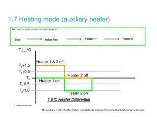
Heater 1 & 2 off. T s +1.5. T s +0.5. Heater 2 off. T s. Heater 1 on. T s -0.5. T s -1.0. Heater 2 on. 1.7 Heating mode (auxiliary heater). The heater on sequence when the system power on. Heater 1 *. Heater 2 *. Start. Indoor Fan. T room ° C. 1.5 ° C Heater Differential.

E N D
Heater 1 & 2 off Ts+1.5 Ts+0.5 Heater 2 off Ts Heater 1 on Ts-0.5 Ts-1.0 Heater 2 on 1.7 Heating mode (auxiliary heater) The heater on sequence when the system power on Heater 1* Heater 2* Start Indoor Fan Troom°C 1.5°C Heater Differential * If available and applicable The auxiliary electric heater feature is available to increase the amount of heat during heat mode.
Auxiliary Electrical Heater Output (HTR1 and HTR2) • There are two output pins (HTR1 and HTR2) on controller main board, which are used to energize the heater contactor. The contactor must be selected accordingly to avoid any safety issue(s). • The heater shall be installed in accordance with local and national legislation. It must comply with EN60335-2-40. • Thermal fuse(s) shall be installed on the heater to eliminate any danger or damage on the heater/unit. This is especially critical when there is any malfunction happen to controller main board or blower. • The heater shall be in a safe location, whereby no risk of damage could be happen on the unit. • Use non-flammable duct for the unit that is installed with heater • Use diff erent power supply for electrical heater and install a circuit breaker for each of the heater. • Maximum temperature in the unit must not exceed 60°C. Temperature measurement shall be taken during the installation or commisioning in order to ensure the temperature not exceed this value. • Select the proper safety device or thermal protector accordingly. • The heater shall never be installed inside the unit. The recommended location for the heater is inside the supply duct, whereby the distance of the heater is sufficient to ensure the temperature inside the unit does not exceed 60°C.