Download
1 / 6
60 likes | 243 Vues
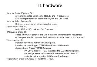
Detector Control System, OK several automates have been added, LV and HV sequences. FSM manages transition between Busy, ON and OFF states. Detector Safety System, OK Detector temperatures within expected range. Slow Control Loop, OK Main 40MHz LHC clock and Fast Command.

E N D
Detector Control System, OK several automates have been added, LV and HV sequences. FSM manages transition between Busy, ON and OFF states. Detector Safety System, OK Detector temperatures within expected range. Slow Control Loop, OK Main 40MHz LHC clock and Fast Command. DAQ system chain, OK added a firmware patch to the ORx mezzanine to increase the robustness of the system in the rare case the frame sent from the detector is corrupted. Trigger system, OK installed new fibers distribution patch panel. installed two new Trigger TOTFED boards with 3 ORxs each. deployed new Trigger TOTFED firmware FW OPTO Receiver FPGA, calculates the CSC hits multiplicity. FW Merger FPGA, calculates which sextant is fires based on majority voting (x out of 5 CSC planes) technique. Trigger chain under test, ready for next 90m * run. T1 hardware
10 10 5 5 5 5 10 10 T1 TRG_TOTFED T1 TRG_TOTFED T1 trigger architecture Trigger Bits 2 x 480 = 960 VFAT 16 In VFAT 16 In CAVERN 1 Sbit 1 Sbit 8 8 ~6k wires ~6k wires x8 x8 VFAT 1 1 VFAT x2 x2 30 30 x2x15 x2x15 CSC CSC T1 ARM T1 ARM Fibers Distribution Box TOTEM TRG _TOTFED + LONEG Mezzanine 44 44 COUNTING ROOM LV1
T1 trigger implementation 1 fiber = 16 Trigger bits Multiplicity encoded in 4 bits 10 10 5+5 OptoRx 1 4bit * 10 out of 64 + To LONEG Inputs 40 out of 64 lines Merger OptoRx 2 + (thr) > (thr) T1_L1 SL + 32 + 12 diff. lines (4bit*5 + 4bit*5) out of 64 SL OptoRx 3 + S-Link 64 Connectors 4bit * 10 out of 64 Trigger code 20/9/11 - Referees
T1 trigger FW implementation (1) OptoRx FPGA Fiber Opto Receiver Tbit Mask Chamber Multiplicity Tbit Sync 16 Tbit 16 16 4 Comp S P #1 CLA Fibers In 10+2 spares 16 Tbit 16 16 4 Comp CLA S P #12 En/Dis En/Dis Programmable Scalers Programmable Scalers 20/9/11 - Referees
T1 trigger FW implementation (2) Merger FPGA CSC Multiplicity comparator Sextant Majority comparator Output stage 4 * 10 OR1 Comp CLA + > 1 bit x Sextant (6 bits) 4 * 10 To LONEG OR2 Comp CLA 1 bit x CSC (30 bits) 4 * 10 (Trigger code) OR3 Comp CLA Programmable Scalers Programmable Scalers Thr Thr 20/9/11 - Referees
T1 trigger HW in IP5 Fibers Distribution Box T1 Trigger TOTFED To LONEG System cabled In IP5