Download
1 / 24
250 likes | 350 Vues
Explore the principles of convection heat transfer in engineering, including modes, resistance concept, and modeling techniques for efficient energy transport in fluid systems. Learn through illustrations and practical examples.

E N D
Reading Materials: Chapter 9 Heat Transfer CONVECTION Heat transfer results from a temperature difference. LAST LECTURE
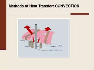
CONVECTION HEAT TRANSFER • Modes • forced • flow induced by external agency e.g. pump • eg. forced-draught air cooler, evaporators • natural • fluid motion caused by temperature-induced density gradients within fluid • Examples • air flow over hot steam pipe, fireplace circulation, cooling electronic devices
CONVECTION HEAT TRANSFER Figure: Natural convection flow over a heated steam pipe
Modelling Convection Forced convection generally most-effective transport of energy from solid to fluid. Engineer's prime concern rate of convection enables sizing of equipment
Modelling Convection Experimentally found that: h - convective heat transfer coefficient. Main problem predict h value for: • variety fluids & flow rates • range of shapes
Resistance Concept Rate equation Written in same form as Ohm’s Law: (Ts-Tb)= driving force (1/hA) – thermal resistance (R) for convection heat transfer.
TYPICAL UNITS FOR h Typical Values
Illustration 27.1 Air at 20°C is blown over an electrical resistor to keep it cool. The resistor is rated at 40,000 ohm and has a potential difference of 200 volts applied across it. The expected mean heat transfer coefficient between the resistor surface and the air is 50 W m-2K-1. What will be the surface temperature of the resistor, which has a surface area of 2 cm2?
SOLUTION Energy Balance Generation = heat loss by convection Rate of heat generation Convective loss
Determining the size (H/T area) of the exchanger (10.25) (10.26) Figure 1. Heat transfer between two flowing fluids separated by a rectangular
Determining the size (H/T area) of the exchanger Figure 2: Heat transfer between two flowing fluids separated by a cylindrical wall (10.27)
Overall heat-transfer coefficient As a short-hand method of describing heat-exchanger performance, we use the overall heat-transfer coefficient, (10.28)
Illustration 27.2 Consider the kettle below. For the conditions given, find the flame temperature for the following values of the heat transfer coefficients: hi (boiling) = 4000 W m-2K-1ho (gas flame) = 40 W m-2K-1
Solution Plane slab- area constant, eliminate A:
Determining the size (H/T area) of the exchanger (10.28) • The term Tavg in equation 10.28 represents the temperature difference between the hot and cold streams averaged. • For single-pass exchangers, the appropriate form of Tavg is the log-mean temperature difference, Tlog mean (often abbreviated LMTD), defined as (10.29)
Determining the size (H/T area) of the exchanger (10. 30) For shell-and-tube exchangers, the inside area (Ai) of the tubes is smaller than the outside area (Ao). However, the differences between Ai and Ao will be neglected.
Saturated Steam, 280oF, mstream Saturated water, 280oF, mstream Hot Cold Oil, 35oF, 960 lbm/min Oil, 110oF, 960 lbm/min Example Balance on cold stream:
Saturated Steam, 280oF, mstream Saturated water, 280oF, mstream Hot Cold Oil, 35oF, 960 lbm/min Oil, 110oF, 960 lbm/min Example How much area is required for the counter-current heat exchanger in Example 10.5? 1 2
Example From table 10.5
Example How much area is required for the co-current heat exchanger in Example 10.5? 1 Saturated water, 280oF, mstream Saturated Steam, 280oF, mstream Hot 2 Cold Oil, 35oF, 960 lbm/min Oil, 110oF, 960 lbm/min
Example From table 10.5