Mathematical Modeling of Physical Systems: Guidelines for Effective Plant Operations
This guide focuses on employing mathematical principles to effectively model the operation of physical plants. It addresses the relationships among key variables and emphasizes the impact of inputs on outputs. Guidelines are provided for selecting significant variables and utilizing standard physical laws to formulate equations, with a strong recommendation against inventing new laws. Concepts of input/output models, state-space representation, and transfer functions are outlined, along with fundamental physical laws governing electrical circuits, motion, and dynamics, aiding in creating accurate models for various systems.

Mathematical Modeling of Physical Systems: Guidelines for Effective Plant Operations
E N D
Presentation Transcript
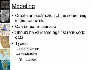
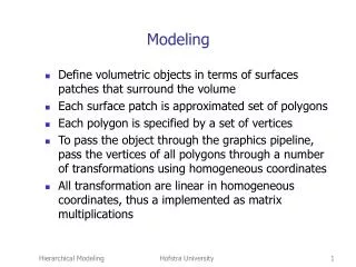
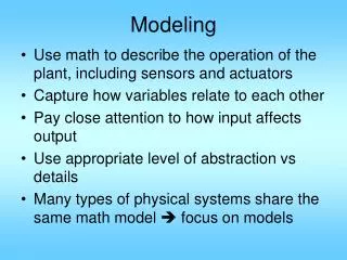
Modeling • Use math to describe the operation of the plant, including sensors and actuators • Capture how variables relate to each other • Pay close attention to how input affects output • Use appropriate level of abstraction vs details • Many types of physical systems share the same math model focus on models
Modeling Guidlines • Focus on important variables • Use reasonable approximations • Write mathematical equations from physical laws, don’t invent your own • Eliminate intermediate variables • Obtain o.d.e. involving input/output variables I/O model • Or obtain 1st order o.d.e. state space • Get I/O transfer function
Common Physical Laws • Circuit: KCL: S(i into a node) = 0 KVL: S(v along a loop) = 0 RLC: v=Ri, v=Ldi/dt, i=Cdv/dt • Linear motion: Newton: ma = SF Hooke’s law: Fs = KDx damping: Fd = CDx_dot • Angular motion: Euler: Ja = St t = KDq t = CDq_dot
Electric Circuits Voltage-current, voltage-charge, and impedance relationships for capacitors, resistors, and inductors impedance admittance
RLC network KVL:
Zf Iin=0 Zi Vin=0 Gain = inf Ideal Op amp:
Mesh analysis Mesh 2 Mesh 1
Write equations around the meshes Sum of impedance around mesh 1 Sum of applied voltages around the mesh Sum of impedance common to two meshes Sum of impedance around mesh 2
Nodal analysis i3 i1 Kirchhoff current law at these two nodes i2 i4 i1 - i2 - i3=0 i3 - i4 =0
Kirchhoff current law conductance
Sum of injected current into each node Sum of admittance at each node Admittance between node i and node j
Op Amp circuit example Note: ip1=0, ∴vp1=vo=vA & vB=vp2=0 Let vC1 & vC2 be s.v., vo output.
KCL at A: vo is not s.v. nor input, use vo=vC2
KCL at B: 0 vo1 not s.v. nor input, vo1=vA+vC1=vn1+vC1 =vp1+vC1=vo+vC1 =vC2+vC1