Understanding SDL as a Network Protocol Specification Language
Learn about the purpose, application, features, and components of SDL for specifying telecommunications systems clearly and unambiguously. Discover the static and dynamic aspects, decoding system structure, and practical examples. Master the graphical and textual representations, system reactions, process instances, and SDL syntax. Dive into system decomposition, dynamic behavior, and process management with SDL.

Understanding SDL as a Network Protocol Specification Language
E N D
Presentation Transcript
NETW 703 Network Protocols SDL Part I Dr. Eng Amr T. Abdel-Hamid Winter 2006 Based on Lectures notes from: * Oleg Chistokhvalov, LUT, IT Dep.
Avg. = 55.8 2/33
Outline • Introduction to SDL • Purpose & Application • Key SDL features • Static SDL Components • Description of the System Structure • Concepts of System, Block and Process • Communication Paths: Channels, Signals • Dynamic SDL Component • State, Input, Output, Process, Task, Decision, Procedure … • Data in SDL • Inheritance • Block and Process Sets • Examples 3/33
Why SDL exists ? • The purpose of SDL is to be a language for unambiguous specification and description of the structure, behaviour and data of telecommunications systems. • The terms specification and description are used with the following meaning: • a specification of a system is the description of its required behaviour • a description of a system is the description of its actual behaviour, that is its implementation 4/33
Where SDL may be used ? • SDL may be used for producing • Specification and Design of diverse applications: aerospace, automotive control, electronics, medical systems, • Telecommunications Standards and Design for (examples): • Call & Connection Processing, • Maintenance and fault treatment (for example alarms, automatic fault clearance, routine tests) in general telecommunications systems, • Intelligent Network (IN) products, • Mobile handsets and base stations, • Satellite protocols, • Increasingly used to generate product code directly with help of tools like ObjectGeode, Tau/SDT, Cinderella 5/33
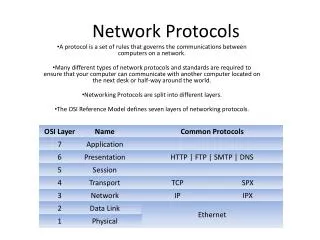
SDL Representations • SDL has two representation forms • SDL-GR - graphical representation • SDL-PR - textual, phrase representation • SDL-PR is conceived as for easily processed by computers - common interchange format (CIF) • SDL-GR is used as a human interface • SDL-GR has some textual elements which are identical to SDL-PR (this is to allow specification of data and signals) • Z.106 recommendation defines CIF with purpose of preserving all graphical information SDL-GR SDL-PR Common Syntax 6/33
System & Environment • The SDL specification defines how Systems reacts to events in the Environment which are communicated by Signals sent to the System • The only form of communication of an SDL system to environment is via Signals SDL System signals ENVIRONMENT 7/33
Process Instance SDL Overview - Blocks System (or another block) Block • Large number of process without structure leads to loss of overview • Blocks are used to define a system structure • Signal routes transfer signal immediately while channels may be delaying Block Process Instance Block Block signal routes channels 8/33
SDL Overview - Process • A process is an agent that contains an extended finite state machine, and may contain other processes. • A System is composed of a number of communicating process instances System Instance signals signals signals Process Instance Process Instance signals 9/33
Static & Dynamic SDL • SDL has a static component, and a dynamic component. • The Static component describes/specifies system structure • Functional decomposition to sub-entities • How they are connected • What signals they use to communicate • The Dynamic component describes/specifies system operation - behavior • SDL Transitions, Transitions Actions • Communications • Birth, Life and Death of Processes 10/33
Static SDL • System is the highest level of abstraction • A system can be composed of 1 or more blocks • A block can be composed of processes and blocks • Processes are finite state machines, and define dynamic behavior System Block Process 11/33
System Decomposition • When dealing with large and complex systems it is best to decompose down to the manageable size functional components: BLOCKs (“Divide and Conquer”). • Follow natural subdivisions: BLOCKs may correspond to actual software/hardware modules. • Minimise interfaces between BLOCKs in terms of the number and volume of signals being exchanged. 12/33
Decomposition Rules:No Limit in number of Block levels 14/33
Decomposition Rules:Blocks and Process cannot share a level 15/33
Dynamic Behavior • A PROCESS exists in a state, waiting for an input (event). • When an input occurs, the logic beneath the current state, and the current input executes. • Any tasks in the path are executed. • Any outputs listed are sent. • The state machine will end up in either a new state, or return to the same state. • The process then waits for next input (event) 16/33
process calling 1/5 wait_for_connection T1 connectTone onHook busyTone reset (T1) reset (T1) VIA uG connectTone connEnd VIA uG connEnd TO TO otherPid otherPid connected set ( NOW idle + T_10sec, T2) Connected wait_for_onHook Process Diagram Example 17/33
PROCESS • PROCESS specifies dynamic behaviour • Process represents a communicating extended finite state machine. • each have a queue for input SIGNALs • may output SIGNALs • may be created with Formal PARameters and valid input SIGNALSET • it reacts to stimuli, represented in SDL by signal inputs. • stimulus normally triggers a series of actions such as data handling, signal sending, etc. A sequence of actions is described in a transition. • PROCESS diagram is a Finite State Machine (FSM) description 18/33
One Very Simple FSM 19/33
state_a state_a sig_a sig_c Process Diagram Components • STATEs: point in PROCESS where input queue is being monitored for arrived SIGNALs • subsequent state transition may or may not have a NEXTSTATE • INPUT: indicates that the subsequent state transition should be executed if the SIGNAL matching the INPUT arrives • INPUTs may specify SIGNALs and values within those SIGNALs • Inputs can also specify timer expiry • OUTPUT: specifies the sending of a SIGNAL to another PROCESS 20/33
Process Diagram 21/33
do_something make_ decision true false A A Process Diagram Components • TASK: description of operations on variables or special operations • The text within the TASK body can contain assign statements. DECISION: tests a condition to determine subsequent PROCESS flow • JOIN: equivalent to GOTO. 22/33
sig_c Process Diagram Components ... • SAVE: specifies that the consumption of a SIGNAL be delayed until subsequent SIGNALs have been consumed • the effect is that the SAVEd SIGNAL is not consumed until the next STATE • no transition follows a SAVE • the SAVEd SIGNAL is put at the end of the queue and is processed after other SIGNALs arrive • START: used to describe behaviour on creation as well as indicating initial state • Similar shape to state only with semi-circular sides 23/33
sigA PROCEDURE ProcB fpar player PId; ProcB (SENDER) Gameid to player stateC Procedure • PROCEDURE: similar to a subroutine • allow reuse of SDL code sections • reduce size of SDL descriptions • can pass parameters by value (IN) or by reference (IN/OUT) 24/33
sig_a sig_a sig_c Priority & Internal Inputs • Priority inputs are inputs that are given priority in a state • If several signals exist in the input queue for a given state, the signals defined as priority are consumed before others (in order of their arrival) • Internal Input/Outputs signals are used for signals sent/received within a same FSM or SW component • There is no formal definition when they should be used. 25/33
* * Shorthands - All Other Input/Save • The Save with an asterisk covers all possible signals which are not explicitly defined for this state in other input or save constructs • The input with an asterisk covers all possible input signals which are not explicitly defined for this state in other input or save constructs 26/33
- Shorthands - Same State • When next state is same as current state the “dash” symbol may be used instead of state name. • This is particularly useful in combination with * (any state) 27/33
Shorthands Example 28/33
DCL numthings INTEGER; StateA SigA numthings = numthings +1; numthings > 7 Specification of Data in SDL • SDL diagrams can contain variables • Variables are declared using the DCL statement in a text box. • Variables can set in a task box and read in decisions • A data type is called a sort in SDL 29/33
ProcessA offspring > 0 true false Dynamic Processes • Processes can be created and destroyed in SDL • Each process has a unique process id. The self expression returns the process id of the current process. • Processes are created within a SDL process using the CREATE symbol. The Create body contains the type of the process to create • The offspring expression returns the process id of the last process created by the process. • The PROCESS that is created must be in the same block as the process that creates it. • The Stop symbol is used within the SDL PROCESS to signify that the process stops. 30/33
Predefined Sorts (types) in SDL • INTEGER: signed integer • NATURAL: positive integer • REAL: real, float • CHARACTER: 1 character • CHARSTRING: string of characters • BOOLEAN : True or False • TIME: absolute time, date (syntype of REAL) • DURATION: a TIME minus a TIME (syntype of REAL) • PID: to identify a process instance 31/33
Operators on Predefined Sorts • Operations := (assignment) , = (equality) and /= (nonequality) are defined for all sorts • INTEGER -, +, *, /, >, <, >=, <=, Float (Integer to Real), Mod (modulo), Rem (remainder) • REAL -, +, *, /, >, <, >=, <=, Fix (Real to Integer) • NATURAL Like Integer • CHARACTER Chr (Integer to Char), Num (Char to Integer), >,<,>=,<= • CHARSTRING Mkstring (Char to Charstring), Length, First, Last, // (concatenation), Substring • BOOLEAN True, False, NOT, AND, OR, XOR • PID Self, Sender, Offspring, Parent 32/33
Timer T7; SET(NOW +20ms,T7) WaitForTimer T7 SigA RESET(T7) Specification of Timers in SDL • Timer is an object capable of generating an input signal and placing this signal to the input queue of the process. Signal is generated on the expiry of pre-set time. • SET(NOW+20ms,T7): sets a T7 timeout in 20ms time. • RESET(T7): cancels the specified timeout. 33/33
Communication Related SDL Terms • signal: • The primary means of communication is by signals that are output by the sending agent and input by the receiving agent. • stimulus: • A stimulus is an event that can cause an agent that is in a state to enter a transition. • channel: • A channel is a communication path between agents. 34/33
Text Symbol • Text Symbol is used to group various textual declarations • It can be located on any type of diagram Text Box Example 35/33
System Diagram • Topmost level of abstraction - system level • Has a name specified by SYSTEM keyword • Composed of a number of BLOCKs • BLOCKs communicate via CHANNELs • Textual Descriptions/Definitions • Signal Descriptions • Channel Descriptions • Data Type Descriptions • Block Descriptions 36/33
SIGNAL S1, S2, S3, S4,S5 ; C1 [S1,S2] Example System Diagram Signal Descriptions in text symbol SYSTEM s C2 [S3] B1 Signal Lists C4 [S5] C3 [S4] B1 Frame symbol - boundary between system and environment Blocks Channels 37/33
SIGNAL doc (CHARSTRING), conf, ind (MsgTyp), req (MsgTyp); Signals • Signals are the actual messages sent between entities • Signals must be defined before they can be used: <signal specification> ::= signal <signal name> [(<sort name>{,<sort name>}*)] {, <signal name> [(<sort name>{,<sort name>}*)]}*; Example: 38/33
Status(True) Signals with parameters • Signals can have parameters known as a sortlist • The signal specification identifies the name of the signal type and the sorts of the parameters to be caried by the signal • Example: signal Status(Boolean); • When signals are specified to be carried on certain channels only signal names are required • When signals are actually generated in the process the actual parameters must be given • Example: 39/33
Signal Lists • A signal lists may be used as shorthand for a list of signal identifiers Example: 40/33
Channel • CHANNEL is connected between Blocks or Block and the Environment. • May be uni- or bi-directional • It may have an identifier (C1) and may have list of all signals it caries • It is an FIFO queue which may introduce an variable delay C1 [S1,S2] Uni-directional delaying Channel C2 [S1,S2] [S3,S4] Bi-directional delaying Channel 41/33
Non-Delaying Channels • Non delaying channels do not introduce any delay in transmission of signals C1 [S1,S2] Uni-directional non-delaying Channel C2 [S1,S2] [S3,S4] Bi-directional non-delaying Channel 42/33
Block Diagram • Has a name specified by BLOCK keyword • Contains a number of Processes • May also possibly contain other BLOCKs (but not mixed with Processes) • Processes communicate via Signal Routes, which connect to other Processes or to Channels external to the Block • Textual Descriptions/Definitions • Signal Descriptions for signals local to the BLOCK • Signal Route Descriptions • Data Type Descriptions • Process Descriptions 43/33
Example Block Diagram Signal Routes Process 44/33
Signal Route • SIGNALROUTE: provide a signal path between processes • similar to CHANNELs except there is no delay involved • Can be bi-directional or unidirectional • Contains a signal list, constraining what signals can sent through it. • In SDL2000 Signal-Route concept is obsolete. Signal Routes are replaced by non-delaying Channels 45/33
Packages & Libraries • Since SDL 92 reusable components may be defined as types and placed into libraries called packages • This allow the common type specifications to be used in more then a single system • Package is defined specifying the package clause followed by the <package name> • A system specification imports an external type specification defined in a package with the use clause. 46/33
Package Example 47/33
SDL Entity Visibility Rules • Entities are • Packages, agents (system, blocks, processes), agent types, channels, signals, timers, interfaces, data types, variables, sorts, signal lists; • Possible Scope Units are • Agent diagrams (System, Block, Process), Data Type Definitions, Package diagrams, task areas, interface definitions ... • The Entity is visible in the scope unit if • is defined in a scope unit • the scope unit is specialisation and the entity is visible in base type • the scope unit has a “package use clause” of a package where entity is defined • the scope unit contains an <interface definition> where entity is defined • the entity is visible in the scope unit that defines that scope unit 48/33
Additional Structural Concepts in SDL • A tree diagram can be constructed to illustrate the hierarchy of the entire SYSTEM . • Macros can be used to repeat a definition or a structure. They are defined using the MACRODEFINITION syntax . • Paramaterised types exist using the generator construct • Gates • A gate represents a connection point for communication with an agent type, and when the type is instantiated it determines the connection of the agent instance with other instances 49/33
system ATM /* This model corresponds to an Automated use bank_lib; Teller Machine (ATM). Banking transactions are performed by means of cash card. This ATM allows cash withdrawal only. Withdrawals must be authorized by the consortium, and in case of success, must be reported to the consortium. */ Consortium ce_ui Customer UI Central q_accept, r_accept, card, display_wait, card, wdrok go_ATM, entry, print, entry, stop_ATM cashtaken, cash, cashtaken, quit eject, quit go_ATM, stop_ATM ATM Example - System Diagram 50/33