Advances in CLIC DDS High Phase Advance Structures: Analysis of Merits and Demerits
This study evaluates the High Phase Advance (HPA) structures within the CLIC Drive Beam Decelerator System (DDS). The research, conducted by a collaboration from the University of Manchester and CERN, highlights the merits and demerits of various cell configurations, focusing on fundamental and dipole mode properties, bandwidth comparisons, and the impact of varying group velocities on power absorption during breakdown. The incorporation of Silicon Carbide (SiC) for enhanced damping is discussed, along with future directions to optimize these structures for improved performance.

Advances in CLIC DDS High Phase Advance Structures: Analysis of Merits and Demerits
E N D
Presentation Transcript
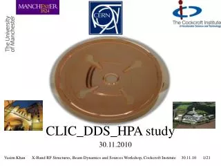
CLIC_DDS_HPA study 30.11.2010
CLIC_DDS Study Collaboration • Vasim Khan • Alessandro D’Elia • Roger Jones University of Manchester and Cockcroft institute, U.K. CERN, Switzerland • Alexej Grudiev • Germana Riddone • Vadim Soldatov • Walter Wuensch • Riccardo Zennaro
Outlook • High Phase Advance (HPA) Structures: Merits and Demerits • CLIC_DDS_HPA • Future of CLIC_DDS_HPA
High Phase Advance Structures 1) Low group velocity → Less power absorbed during breakdown Ref: R.M. Jones, et. al., SLAC-PUB 8887 CLIC
NLC: Band partitioning NLC: DS1 a = 4.23 mm ψacc : 120°→ 150°:Lowest dipole kick factor reduces by ~ 20% Ref: R.M. Jones, et. al., SLAC-PUB 9467
Dipole mode properties 120deg. Γx = 0.0126 150deg. Γx = 0.021 Cell # 1 a=4.0 mm, t=3.2 mm Cell # 1 a=4.0 mm, t=4.0 mm
DDS_HPA: Merits and Demerits • Reduction in dipole bandwidth from 2.1 GHz to 1.8 GHz • Necessary to reduce bunch population to satisfy wakefield constrains • Luminosity reduction Merits Demerits • Reduced input power • Less power absorbed during breakdown • Kick factors reduced • Better dipole coupling • Cost efficient ?
Enhanced damping: Eight manifolds Four regular and four additional manifolds Significant coupling
Cell # 1 Cell parameters a = 4.3 mm t = 2.6 mm Rc = 9.0 mm Mr = 2.0 mm Mc = 15.1 mm Fundamental mode properties Q=7080 R’/Q=10.356 (kΩ/m) vg=2.44 (%c) Es/Eacc=2.22 Hs/Eacc=4.3 (mA/m) Sc/Eacc=5.45 x 10-4 (W/μm2/Eacc2) fsyn=16.1 GHz Dipole mode properties
Cell # 24 Cell parameters a = 2.5 mm t = 2.8 mm Rc = 8.8 mm Mr = 2.0 mm Mc = 15.1 mm vg=0.32 (%c) fsyn=17.89 GHz
Two Cell result Need improvement Lowest dipole mode properties Δf=2.25 σ=1.78 GHz Δf/fc= 10.5 (%c)
Eight manifolds and Sic As the coupling in the last cell is poor it is important to enhance coupling by optimising the last cell Additional manifold εr=13 tanδ=0.02 NMr=2.8 Damp_r=1 Damping material Regular manifold
Accelerating mode NMr=2 .8 Damp_r=1 εr=14 tanδ=0.04
DDS_HPA_SiC • SiC insertion in an 8-manifold cell improves damping • The SiC properites and dimensions are optimised for Cell # 24 • This optimisation does not improve damping of Cell # 1 • Due to SiC losses, multiple avoided crossings are observed • Need some modification in circuit model to incorporate additional losses (SiC) (future work ?)
Closing remarks • CLIC_DDS_HPA: 1) Coupling looks promising 2) Need to improve bandwidth • To be investigated in detail: 1) Eight manifolds 2) DDS_SiC damping 3) Circuit model modification to incorporate SiC losses
Acknowledgments • We have benefited from discussions with Juwen Wang, Zhengai Li and Toshiyasu Higo on X-band structures • Thanks to Igor Syratchev for suggesting to investigate CLIC_DDS_SiC. Thank you
Four manifolds Cell # 1 Cell # 24 Fsyn~15.76 GHz Fsyn~17 GHz Cell parameters a = 3.3 mm t = 3 mm Rc = 9.0 mm Mr = 2.0 mm Mc = 15.1 mm vg = 0.95 (%c) Cell parameters a = 4.6 mm t = 2 mm Rc = 9.0 mm Mr = 2.0 mm Mc = 15.1 mm vg = 3.6 (%c) Cell # 1 Cell # 24
Cell # 1 Cell parameters a = 4.6 mm t = 2 mm Rc = 9.0 mm Mr = 2.0 mm Mc = 15.1 mm vg = 3.6 (%c) Fsyn~15.77 GHz
Cell # 24 Cell parameters a = 3.3 mm t = 3 mm Rc = 9.0 mm Mr = 2.0 mm Mc = 15.1 mm vg = 0.95 (%c) Fsyn~17 GHz
Cell # 1 Cell parameters a = 4.6 mm t = 2 mm Rc = 9.0 mm Mr = 2.0 mm Mc = 15.1 mm vg = 3.6 (%c) Fsyn~15.77 GHz
Cell # 24 Cell parameters a = 3.3 mm t = 3 mm Rc = 9.0 mm Mr = 2.0 mm Mc = 15.1 mm vg = 0.95 (%c) Fsyn~17 GHz
Cell # 1 Cell parameters a = 4.6 mm t = 1 mm Rc = 9.0 mm Mr = 2.0 mm Mc = 15.1 mm vg = 4.84 (%c) Fsyn~15.65 GHz