Download
1 / 15
150 likes | 311 Vues
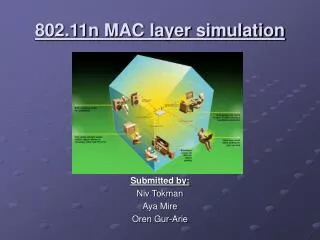
Simulation of VoIP traffic in 802.11n networks. Aya Mire Niv Tokman Oren Gur-Arie. Contents. 802.11n Packet aggregation Project goals Project assumptions Implementation Simulation flow Milestones. 802.11n. Based on IEEE 802.11 – Standard for wireless computer networks

E N D
Simulation of VoIP traffic in 802.11n networks Aya Mire Niv Tokman Oren Gur-Arie
Contents • 802.11n • Packet aggregation • Project goals • Project assumptions • Implementation • Simulation flow • Milestones
802.11n • Based on IEEE 802.11 – Standard for wireless computer networks • Providing ability of working in a rate of at least 100Mbps. • Support work with MIMO – several transmitters and receivers for each station • Reverse direction communication • Packet Aggregation • Still under development - TGn
Packet aggregation • Reduces the overhead of control packets and timeouts related to the 802.11 protocol • May be destined to single or multiple receivers
Project goals • Examine the influence of aggregated communication on periodic information – with focus on VoIP • Examine the influence of aggregation size (number of packets per aggregation) on network’s behavior
Project assumptions • Centralized network environment (star topology) • VoIP data only (of two types: 10ms, 60 bytes and 20ms, 80 bytes) • Aggregation is done only by AP • No ACKs
Simulation manager Statistics manager Conversation Generator STA Network AP STA STA Implementation
Simulation manager • Handles the main loop of the simulation – the time counter (in step of 1us) • Gathers the statistics from the different units of the system • Manages the conversation generators
Regular station (STA) • Represents a wireless client. • Each STA contains Tx and Rx FIFOs for both sending and receiving messages. • Data traffic between STAs goes through the AP. • STA generate and handles the different control messages defined by 802.11n protocol
AP • Similar implementation and behavior to STA. • Buffers data from different STA until aggregation threshold is reached, or time limit has expired.
Network unit • Simulates the traffic “on the air” • Serves as a “pipe” between STAs and AP (and vise-versa) • Inserts error into transmitted messages • Detects collisions of packets (and flags them as erroneous)
VoIP data generators • Generate VoIP data packets and inserts them to the STA’s Tx FIFOs • Generation of data is periodic every 10ms or 20ms, and done simultaneously to two STAs engaging in conversations • Several VoIP generators can work in parallel
Statistic • for each VoIP type: • Total number of messages during simulation time. • Number of messages successfully sent. • Average time of message transmission (from source to destination, via AP). • Average waiting time in AP buffer. • Average time from entering Tx FIFO to actual transmission time. • Statistics without explicit reference to VoIP type: • Number of aggregations less than max aggregation size. • Average number of receivers in aggregation • Number of collisions. • Number of control messages.
Simulation flow 1. Data arrives at Tx FIFO of STA A from VoIP data generator. IAC is sent. 2. AP receives IAC, wait SIFS and respond with RAC. 3. RAC received. STA A sends non-aggregated VoIP data 4. After DIFS, the operation is repeated by STA B 5. Aggregation size is reached. AP send IAC followed by the aggregated data 6. Data is received by STA C
Project time table • Week 1-2: Headers + Classes (data and methods), Statistics unit • Week 3-5: STA, AP and Network unit • Week 6: Simulation manager, data generators • Week 7: Integration and testing, analyze simulation’s results