Download
1 / 37
390 likes | 654 Vues
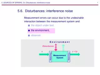
E n v i r o n m e n t. Matching. Matching. 5. SOURCES OF ERRORS. 5.6. Disturbances: interference noise. 5.6. Disturbances: interference noise. Measurement errors can occur due to the undesirable interaction between the measurement system and:. the object under test,. the environment,.

E N D
E n v i r o n m e n t Matching Matching 5. SOURCES OF ERRORS. 5.6. Disturbances: interference noise 5.6. Disturbances: interference noise • Measurement errors can occur due to the undesirable interaction between the measurement system and: • the object under test, • the environment, • observer. Disturbance +Dy x y Measurement System
5. SOURCES OF ERRORS. 5.6. Disturbances: interference noise • There are two types of disturbances (interference noise): • additive disturbance, • multiplicative disturbance. • To quantify the effect of additive disturbances on the measurement system, the disturbance sensitivity (or sensitivity factor) is used: Dy Dd dy dd ___ Sd ___ . x=0 x=0 Disturbance, d (DVCC ) Measurement System Dy x=0 dy=Sd dd (SVCC [Dy/V] supply voltage sensitivity)
5. SOURCES OF ERRORS. 5.6. Disturbances: interference noise • Additive disturbances can be written as the equivalent disturbing input signal Sd Sx xeq___ Dd , • where Sx is the sensitivity of the measurement system: dy dx . Sx = ___ Disturbance, d Measurement System dy=Sx xeq x+xeq y+Dy
5. SOURCES OF ERRORS. 5.6. Disturbances: interference noise • Multiplicative disturbances affect the sensitivity Sx of the measurement system. Disturbance, d (DT) x y+Dy dy=(Cd dd)·x Sx (CT [ppm/] temperature coefficient) Measurement system • To quantify the effect of multiplicative disturbances, the disturbance coefficient is used: dSx /Sx dd dSx dd Cd ____= _______ 106 [ppm/dd].
5. SOURCES OF ERRORS. 5.6. Disturbances: interference noise Example 1: Supply voltage sensitivity SVCC DVCC DC-voltage null detector DVout= SVCC DVCC VIN =0 DVout VIN =Veq SVCC SVIN DVout= SVIN Veq DC-voltage null detector DVout Veq= ____ DV
5. SOURCES OF ERRORS. 5.6. Disturbances: interference noise Example 2: Temperature coefficient CT T1 RG 1 Instrumentation amplifier, G Vout 1 VS dG dT CT = ____ 106 [ppm/º] T2 Vout 2 - Vout 1 Vout 1 RG 2 __________ dVout= Instrumentation amplifier, G dVout=(CT DT)·VS Vout 2 VS
5. SOURCES OF ERRORS. 5.6. Disturbances: interference noise. 5.6.1. Reduction of the influence of disturbances 5.2.1. Reduction of the influence of disturbances • 1. Isolate the measurement system. For example, use electro-magnetic shielding, stabilize the ambient temperature, etc. • Separate the effect of disturbances on the output of measurement system to correct the measurements. For example, suppress the input signal and measure the output signal due to the additive disturbance only. Then correct the measurements with the input signal applied. • 3. Change the input signal in such away to avoid the disturbance. For example, translate a dc signal into ac one to avoid dc offset and drift and flicker noise. • 4. Split the measurement system (or only its critical part) into two parallel or series channels and use parallel, series, or ratio compensation to compensate the disturbance.
5. SOURCES OF ERRORS. 5.6. Disturbances: interference noise. 5.6.1. Reduction of the influence of disturbances Example Compensation: d parallel S1 Sd1 = -Sd2 x y d S1 Cd1 = -S2 Cd2 S2 series d d Sd1 S2 = -Sd2 x y Object Sensor S1 S2 Cd1 = -Cd2 d ratio S1 Any ratio measurement system x y not effective d Cd1 = Cd2 S2
5. SOURCES OF ERRORS. 5.6. Disturbances: interference noise. 5.6.1. Reduction of the influence of disturbances 5. Use feedback against multiplicative disturbances. DT x y SOL DT x y SOL b
SOL 1+ SOL b _______ 1. Sf = DSOL /SOL DT ________ 2. CT OL = DSf /Sf DT ______ 3. CT f = 1 1+ SOL b SOL SOL SOL b (1+ SOL b)2 1 (1+ SOL b) 1 (1+ SOL b) _________ _________ ____ _______ _________ 4.dSf /dSOL = - = 1 1+ SOL b 5.dSf /Sf = _______ dSOL /SOL 1 1+ SOL b 6. CT f = _______ CT OL 5. SOURCES OF ERRORS. 5.6. Disturbances: interference noise. 5.6.1. Reduction of the influence of disturbances
5. SOURCES OF ERRORS. 5.6. Disturbances: interference noise. 5.6.1. Reduction of the influence of disturbances Note that negative feedback reduces additive disturbances by the same factor as it reduces the sensitivity of the system. This means that the ratio of the measurement signal and the disturbances (both referred to the output or the input) will notchange due to the application of feedback. x+xeq y+Dy SOL b In the same way, the signal-to-noise ratio of the measurement system will alsonot be improved by using negative feedback. (It will be decreased due to the additional noise contribution by the feedback network.) Reference: [1]
5. SOURCES OF ERRORS. 5.6. Disturbances: interference noise. 5.6.2. Sources of disturbances 5.2.2. Sources of disturbances A. Thermoelectricity Metal A Junction at T1 Metal B V = ST (T1-T2) Metal A Junction at T2 Thermoelectricity is an additive disturbance. Reference: [1]
5. SOURCES OF ERRORS. 5.6. Disturbances: interference noise. 5.6.2. Sources of disturbances T1 T2 Cu Pb/Sn Kovar Cu-AgCu-Pb/Sn3 mV/º Cu-Au0.3 mV/º Cu-Kovar500 mV/º Cu-Cd/SnCu-CuO1000 mV/º Reference: [1]
5. SOURCES OF ERRORS. 5.6. Disturbances: interference noise. 5.6.2. Sources of disturbances B. Leakage currents 1 cm (100 MW) V2 V1 Leakage current, IL V2-V1 RL IL = ________ Reference: [1]
5. SOURCES OF ERRORS. 5.6. Disturbances: interference noise. 5.6.2. Sources of disturbances Active guarding Vout AOL V1 Leakage current, IL V1-V1AOL /(1+AOL) 0.5RL V1-Vout 0.5RL 1 1+AOL V1 0.5RL IL = ________ = __________________ = ______ _____
1/jwCp >>ZSIIZin 5. SOURCES OF ERRORS. 5.6. Disturbances: interference noise. 5.6.2. Sources of disturbances C. Capacitive injection of interference Cp ZS vS 220 V 50 Hz Vin Zin Vd Cable Measurement system Vin= Vd jw Cp(ZSIIZin) (ZSIIZin) Vin Inductive injection of interference is an additive disturbance. Reference: [1]
5. SOURCES OF ERRORS. 5.6. Disturbances: interference noise. 5.6.2. Sources of disturbances Electrical shielding: grounding at the source Cp ZS vS 220 V 50 Hz Zin Shielded cable Vd Measurement system ZS <Zin Home exercise: Prove that the grounding of the shield at the end of the cable that is attached to the circuit with the lowest impedance keeps as small as possible the interference voltage between the shield and the signal conductors. Reference: [1]
5. SOURCES OF ERRORS. 5.6. Disturbances: interference noise. 5.6.2. Sources of disturbances Electrical shielding: grounding at the measurement sistem input Cp ZS iS 220 V 50 Hz Zin Shielded cable Vd Measurement system ZS >Zin Reference: [1]
5. SOURCES OF ERRORS. 5.6. Disturbances: interference noise. 5.6.2. Sources of disturbances D. Inductive injection of interference ZS i(t) VS Vd Area, A H(t) Zin Wire loop Measurement system VS Vd ___f(ZS ,Zin) Vd A, di/dt; Inductive injection of interference is an additive disturbance. Reference: [1]
5. SOURCES OF ERRORS. 5.6. Disturbances: interference noise. 5.6.2. Sources of disturbances Reduction of the wire loop area ZS i(t) VS H(t) Vd Zin Wire loop Measurement system A Vd Reference: [1]
5. SOURCES OF ERRORS. 5.6. Disturbances: interference noise. 5.6.2. Sources of disturbances Employment of twisted pair ZS i(t) VS H(t) Vd Zin Twisted pair Measurement system Aeq Vd Reference: [1]
5. SOURCES OF ERRORS. 5.6. Disturbances: interference noise. 5.6.2. Sources of disturbances Magnetic shielding ZS i(t) VS Zin Single-shell or multi-shell magnetic shield Reference: [1]
5. SOURCES OF ERRORS. 5.6. Disturbances: interference noise. 5.6.2. Sources of disturbances E. Injection of interference by imperfect grounding 1) Stray currents. Grounding the measurement object and the measurement system at different points on a ground rail causes additive voltage disturbances due to stray ground currents. ~ N ZS vS Measurement system vd Istray1 Istray2 Rg Istray Reference: [1]
5. SOURCES OF ERRORS. 5.6. Disturbances: interference noise. 5.6.2. Sources of disturbances Single-point grounding helps to reduce the disturbances. ~ N ZS vS Rg Measurement system vd Istray1 Istray2 Istray Reference: [1]
5. SOURCES OF ERRORS. 5.6. Disturbances: interference noise. 5.6.2. Sources of disturbances Differential input and shielded twisted pair further reduce the disturbances. ~ N ZS vS Measurement system (CMRR) vd Istray1 Istray2 Rg Istray Reference: [1]
5. SOURCES OF ERRORS. 5.6. Disturbances: interference noise. 5.6.2. Sources of disturbances 2) Ground loops. If single-point grounding is impossible, ground lops can be a significant source of interference noise: ZS vS Measurement system Ground loop (inductive injection of interference) The effect of multiple-point grounding can be minimized by isolating the two circuits by: (1) transformers,(2) common-mode chokes, (3) optical couplers, or (4) frequency-selective grounding (hybrid grounds). Reference: [2]
5. SOURCES OF ERRORS. 5.6. Disturbances: interference noise. 5.6.2. Sources of disturbances Isolation with: ZS vS Measurement system Isolating device (1) transformers (2) common-mode chokes (3) optical couplers Signal current Common-mode current Balun (balanced, unbalanced signals) Reference: [2]
5. SOURCES OF ERRORS. 5.6. Disturbances: interference noise. 5.6.2. Sources of disturbances Isolation with: (4) frequency-selective grounding (hybrid grounds) is used when the common-noise voltages are at very different frequencies from the desired signal: ZS vS Measurement system Reference: [2]
6. MEASUREMENT SYSTEM CHARACTERISTICS. 6.1. General structure of a measurement system 6. MEASUREMENT SYSTEM CHARACTERISTICS 6.1. General structure of a measurement system Measurement system Memory Measurement object Input transduction Transmission Signal processing Control Exciter User interface User Reference
6. MEASUREMENT SYSTEM CHARACTERISTICS. 6.2. Measurement system characteristics. 6.2.1. Sensitivity 6.2. Measurement system characteristics 6.2.1. Sensitivity • The sensitivity of a measurement system is the ratio of the magnitude of the output signal y to that of the input signal x. • 1) Static sensitivity. y x G = . • 2) Dynamic sensitivity. y x g(x0)= . x=x0 Reference: [1]
6. MEASUREMENT SYSTEM CHARACTERISTICS. 6.2. Measurement system characteristics. 6.2.1. Sensitivity • 3) Scale factor. SF =1/G . Example: Sensitivity and scale factor y=4 div Signal source x=1 mV p-p G=4 div/mV; SF=0.25 mV/div Reference: [1]
6. MEASUREMENT SYSTEM CHARACTERISTICS. 6.2. Measurement system characteristics. 6.2.2. Sensitivity threshold 6.2.2. Sensitivity threshold • The sensitivity threshold, ST, of a measurement system is determined by the smallest signal that can still be detected, with a given probability of success. • To define a measure for the sensitivity threshold let us first define the detection criterionD for an average signal S: s Average signal, S S 2 Detection criterion D t Detection result 1 0 t Reference: [1]
6. MEASUREMENT SYSTEM CHARACTERISTICS. 6.2. Measurement system characteristics. 6.2.2. Sensitivity threshold • A commonly used measure for the sensitivity threshold is the magnitude of the signal for which the SNR=1. • The detection probability is then approximately 70% for a Gaussian noise. DP, % EP, % SNR* f(x) 1 69.15 30.85 Detection probability, DP 1.4 76.02 23.97 2 84.13 15.87 Noise 3 93.32 6.68 N 4 97.72 2.28 5 99.38 0.62 6 99.87 0.13 8 99.9968 0.0032 s S 0 S 10 99.999971 0.000029 2 Error probability, EP Average signal S N S 2 * SNR = , D = Detection criterion, D Reference: [1]
6. MEASUREMENT SYSTEM CHARACTERISTICS. 6.2. Measurement system characteristics. 6.2.3. Resolution 6.2.3. Resolution • The resolution,R, is defined as the smallest interval Dx of the measured signal x that will still cause a change in the measrement result y. • According to the above: RESST s N. • The resolution can also be defined as the ratio of xmax (or full-scale value of x, FS) to Dx: xmax Dx FS ST RES • For example, if xmax =10 V and Dx =150 mV, then RES 216, which corresponds to a resolution of 16 bit. Reference: [1]
6. MEASUREMENT SYSTEM CHARACTERISTICS. 6.2. Measurement system characteristics. 6.2.4. Inaccuracy, … 6.2.4. Inaccuracy, accuracy, and precision • If we define the true magnitude of a signal x as Xtrue, the average measured magnitude as X, the maximum random error as A (uncertainty of type A*), the systematic error as B (uncertainty of type B), and the inaccuracy as D A+B, then f(x) s 3s X x 0 Xtrue B A Inaccuracy, DA+B * International Committee of Measures and Weights, 1986
X 6. MEASUREMENT SYSTEM CHARACTERISTICS. 6.2. Measurement system characteristics. 6.2.4. Inaccuracy, … D Xtrue d 100% • the relative inaccuracy can be defined as: • the accuracy can be defined as: ACC 100% - d (The ability of a measurement to match the actual value of the quantity being measured.) • and the precision can be defined as: A X P(1- )100% (The ability of a measurement to be consistently reproduced.) More accurate, but same precision f(x), normalized More precise and more accurate s 3s x 0 Xtrue B A Inaccuracy, D
Good luck! Thank you and good luck in the final exam!