DIESEL ENGINE
DIESEL ENGINE. ENGINE DEVELOPMENT DIRECTORATE RESEARCH DESIGNS AND STANDARDS ORGANISATION (R.D.S.O.) SAURABH CHAKRABORTY MECHANICAL ENGINEERING FINAL YEAR. ABOUT RDSO. Railways were introduced in 1853. IRCA was set up in 1903, followed by CSO.

DIESEL ENGINE
E N D
Presentation Transcript
DIESEL ENGINE ENGINE DEVELOPMENT DIRECTORATE RESEARCH DESIGNS AND STANDARDS ORGANISATION (R.D.S.O.) SAURABH CHAKRABORTY MECHANICAL ENGINEERING FINAL YEAR
ABOUT RDSO • Railways were introduced in 1853. • IRCA was set up in 1903, followed by CSO. • RTRC was setup in 1952. • In 1957 CSO & RTRC were integrated to form RSSO. CSO + RTRC = RDSO
FUNCTIONS • Technical advisor to Railway Board. • Development of new & improved designs. • Development, adoption, absorption of new technology for IR. • Development of standards for materials & products specially needed by IR. • Technical investigation, statutory clearances, testing & providing consultancy services.
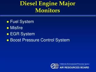
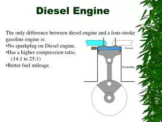
HOW DIESEL ENGINE WORKS • DE relies upon compression ignition. • DE’s compression ratio lies b/w 16:1 and 25:1. • Temp. increases to 700Cto 900C. • Piston approaches TDC, fuel is injected. • Ignition instantly occurs, causing a rapid increase in cylinder temperature & pressure. • Piston is driven downward with great force, pushing on the connecting rod & turning the crankshaft. • Exhaust gases will be used to drive a turbocharger.
TWO STROKE • Intake begins when the piston is near BDC. • Hybrid turbocharger is used, to charge the cylinder. • As the piston rises, compression takes place. • Near TDC, fuel injection occur. • Resulting in combustion, driving the piston downward. • Piston moves down, expelling the combustion gases.
FOUR STROKE • Starting position, intake stoke & compression stroke
ENGINE BASE • Supports the engine block • Serve as oil sump. • Accommodate lube oil main header. • Take lube oil pump & water pump at the free end. • Allow openings for crankcase inspection. • Take fitment of crankcase explosion cover.
ENGINE BLOCK • Most important & very highly stressed structure. • Fitted with- 1) crank shaft 2) cam shaft 3) cylinder heads 4) pistons 5) connecting rods 6) fuel injection pumps 7) turbo support They form a complete power-pack.
CRANK SHAFT • Singular costliest item in diesel engine. • Medium of transforming reciprocating motion to rotary motion. • Balance weights can be either bolted up or welded.
CAM SHAFT • Performs the vital role of opening & closing inlet & exhaust valves. • Allow timely injection of fuel inside the cylinder. • Usually 3 cams for each cylinder- 2 outer cams for exhaust & inlet valves 1 central cam for fuel injection.
CYLINDER HEAD • CH is held on the cylinder liners by 7 hold down studs. • Subjected to high shock stress & combustion temperature at the lower face. • Complicated casting where cooling passages are cored for holding water. • Space had been provided for passage of inlet air & exhaust gases. • Space for fuel injection nozzles, valve guides & valve seat.
LINERS • Forms the wall of the combustion chamber. • Guides the movement of piston. • Mainly of 2 types:- Dry Liner Wet Liner
PISTON • Compresses the air to required pressure & temperature • Receives the thrust of expanding gases & transmits the force through connecting rod. • With the help of piston rings, prevents leakage of gas from combustion chamber.
PISTON RINGS • Seal the combustion chamber • Prevent blow by of air & high temperature combustion gases. • Scraps down excess lube oil from walls of cylinder liner. • Prevents reaching lube oil into combustion chamber.
TYPES OF RING COMBINATIONS 5 RING COMBINATION 6 RING COMBINATION • Square face • Taper face • Taper face • Double taper face • Conformable • Square face • Taper face • Taper face • Double taper face • Double taper face • Conformable
CONNECTING ROD • Connects piston & crank shaft • Medium of converting reciprocating motion to rotary motion • Connecting rod assembly consists of- 1) Connecting rod 2)Connecting rod cap 3)Piston pin bushing 4)Bearing shell upper 5)Bearing shell lower 6)Connecting rod bolts & nuts
FUEL OIL SYSTEM Consists of two integrated systems- FUEL FEED SYSTEM FUEL INJECTION SYSTEM
F.F.S. & ITS ASSOCIATE COMPONENTS • Fuel oil tank • Fuel primary filter • Fuel transfer pump or booster pump • Fuel relief valve • Fuel secondary filter • Fuel regulating valve
F.I.S. • When DE is started, all fuel injection pumps start functioning. • According to firing order, all F.I. pumps start discharging fuel oil to their respective nozzles.
CHARGE AIR SYSTEM • For charge air system Turbo super charger is used in locomotives.
LUBE OIL SYSTEM • It serves the following purposes: Cooling of bearing, pistons etc Protection of metal surfaces from corrosion, rust, surface damages & wear. Keep the components clean & free from carbon.
COOLING SYSTEM Different cooling systems are used: • Air cooling • Water cooling • Oil cooling