Download
1 / 26
280 likes | 562 Vues
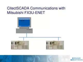
CitectSCADA Communications with Mitsubishi FX3U-ENET. Open FX configuartor-EN to define the FX3U-ENET ethernetcard. And Set module nummer Module 1 = 2de special module at the right side. Operational settings. Select “Binary code” Select “Always wait for open” Give in the IP adress

E N D
Open FX configuartor-EN to define the FX3U-ENET ethernetcard • And Set module nummer Module 1 = 2de special module at the right side
Operational settings • Select “Binary code” • Select “Always wait for open” • Give in the IP adress • PLC1 192.168.3.1 • PLC2 192.168.3.2 • Check all setting andsave these with End
Operational settings • Define one or more ports as MELSOFT connections for GX IEC Developer and FX configutor-EN • Define a port for CitectSCADA • TCP • Unpassive • Procedure exit (MC) • Portnumber 1300 • Check all setting andsave these with End
Write settings to the FX3U-ENET • Push the Write button • Select the right COM-portto connect to the PLCand press OK • Push the Write button todownload the settings • Set the PLC to stop • Click OK on the message • With Yes the PLC comes back in run • Power the PLC OFF and ON to reset the ethernet card
Diagnose via serial • Push the Diagnostics button • Connection interface is still set to a COM-port • Push the Diagnostics button in this window as well • Select the different diagositics tabs
Diagnose via ethernet • Push the Diagnostics button • Change the transfer setupto the IP adress of this PLC • Push the Diagnostics button in this window as well • Select the different diagositics tabs
GX IEC Developer via ethernet • Select the Ethernet board on the PC side • Select the Ethernet module in thePLC side • Give in the IP adressof the PLC • Set the timeout to 5 sec • Press Connection test • Save these setting by closing all windwos with OK
Operational settings • Define one or more ports as MELSOFT connections for GX IEC Developer and FX configutor-EN • Define a port for CitectSCADA • TCP • Unpassive • Procedure exit (MC) • Portnumber 1300 • Check all setting andsave these with End
Open Citect project en start de Express Communications wizard
Express Communications wizard steps • IOserver • name = IOserver • IOdevice • name = PLC1 • external I/Odevice • Mitsubishi FX Serie FX3UEthernet(TCP/IP) • Adress 255 (host PLC) • IP adress en port are not asked. See next page.
Set IP - and port adress • Open de port settings of PLC1 • Set the special opt-i10.10.10.160 -p1300 • Press replace to save settings (PLC has IP adress 10.10.10.160 and port 1300 open for Citect)
Cluster needed in Citect v7 • Open clusters • Make a cluster and press “Add” • Open I/O servers • Attach your IOServer to a your cluster and press Replace
Open Variable tags and define tags • Define a 16 bits tag • Name = RegD0_PLC1 • Adress = D0 • IO Device Name = PLC1 • Data type = INT • Press add • Define a 16 bits tag • Name = RegX0_PLC1 • Adress = X0 • IO Device Name = PLC1 • Data type = Digtal • Press add
Place a register on the page • Past genie • Select libary keyentery • Select parameter2 • Press OK • Set tag • Press OK • Move object and resizeto your wish
Place a register on the page • Set symbol • Place it on the page • Insert a tag • Press OK
Check your Communications settings Cluster1 > IOServer > BOARD1 > PORT1_BOARD1 > PLC1 > D0_PLC1 PORT • IP adres ENET192.168.3.1 • Portnumber ENET1300 • Special Opt-i10.10.10.160 –p1300 • Default TCP & BIN IO DEVICE • Adress255 (host) • ProtocolMELSCNET1 Tag = D0_PLC1
Run your project in demo mode • Run your project • Press OK and run in demo mode for 15 minutes • Via menu update pages and select page01
Connect more FX3U-ENET modules • Open de ports • Change • portname to PORT2_BOARD1 • Port Number to 2 • IP adress to 10.10.10.X • Press Add • Open de IOdevices • Change • Name to PLC2 • Number to 2 • Press Add • You have now 2 record of ports and of IOdevices
Define tags of PLC2 • Open the tag RegD0_PLC1 • Change • Name to RegD0_PLC2 • IO Device Name to PLC2 • Press add • Open the tag RegX0_PLC1 • Change • Name to RegX0_PLC2 • IO Device Name = PLC2 • Press add
Add the PLC2 object on the page • Copy the 2 objectfrom PLC1 • Change the tagsof the copiedobjects • Close the pageand save it