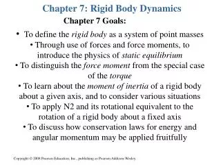
CHAPTER 7. CIRCUIT DYNAMICS
CHAPTER 7. CIRCUIT DYNAMICS. Circuit Theory PoliTong – A.A. 2010-2011. M. Repetto, Dipartimento di Ingegneria Elettrica - Politecnico di Torino S. Leva, Dipartimento di Energia – Politecnico di Milano. I. Introduction: time as a new dimension in circuits.

CHAPTER 7. CIRCUIT DYNAMICS
E N D
Presentation Transcript
CHAPTER 7.CIRCUIT DYNAMICS Circuit Theory PoliTong – A.A. 2010-2011 M. Repetto, Dipartimento di Ingegneria Elettrica - Politecnico di Torino S. Leva, Dipartimento di Energia – Politecnico di Milano
I. Introduction: time as a new dimension in circuits • resistive networks answer instantaneously to any input so that network variables, even if supplied with a time-varying source, follow the input behavior and each time instant is independent on the previous one • this behavior is due to the algebraic nature of the constitutive equations that links together only network variables at the same time instant • if circuit contains also C and L this is not true anymore: time derivative contained in C and L constitutive equations takes into account also the rate of variation of network variables and thus the response of the system is dynamic • even if writing the equation of the circuit is the same as for resistive networks, now its solution requires the integration of a ordinary differential equation (ODE)
I. Introduction: ordinary differential equations • the sets of equations used to solve the circuit are the same as before (constitutive equations and Kirchhoff voltage and current law) but the final system of equations is now of differential type • it can be proved that linear circuits give rise to final equations which are linear ordinary differential equations with constant coefficients • among the class of ODE these ones are the only one to have a standard method of solution
I. Introduction: ordinary differential equations • following the Cauchy method, due to ODE linearity, the solution can be found by adding up two contributes: • homogeneous solution or natural response: the natural response or transient response is the circuit’s temporary response that will die out with time. • particular solution or forced response: the forced response or steady-state response is the behavior of the circuit a long time after an external excitation is applied.
II.1. State variables • On the circuit point of view the elements that can storage energy are the inductor and the capacitor. The quantities from which depend on the energy are: • the current in an inductor • the voltage across the capacitor The energy is a state function that means that the energy can not change suddenly (no real component can supply infinite power)
6 II.1. State variables • The current in a inductor and the voltage across a capacitor are called state variables. • The state variables: • are continuous function of time and can not have discontinuities • characterize the dynamic of the network NO
7 II.2. Network variables • All the other quantities (voltage and current in R, voltage across L, current flowing iin C, current flowing in E, voltage across A) are called network variables. Their evolution can be calculated starting from the one of state variables. • These quantities can have discontinuities.
II.3. Switches in circuits SHORT 1 SHORT 1 OPEN OPEN t t 0 0 t t 0 0 8 • one way to create a time varying input is to use a constant voltage or current generator and connecting it to the circuit by means of a switch • a switch is a component which toggles between the states of open and short circuit 2 1 SHORT CIRCUIT OPEN CIRCUIT OPEN CIRCUIT 3 SHORT CIRCUIT • Two different conditions: • 1,2 SHORT CIRCUIT • and 1-3 OPEN CIRCIT • 1,3 SHORT CIRCUIT • and 1-2 OPEN CIRCIT t<t₀ OPEN CIRCUIT t≥t₀ SHORT CIRCUIT t<t₀ SHORT CIRCUIT t≥t₀ OPEN CIRCUIT
III.1. Dynamic analysis of LTI network without L or C 9 E=10V R=5Ω The switch S is short-circuited at t=0. Find i from 0¯ to + i(0¯)=0 for t < 0 the switch is open so that no network variable is different from zero for t > 0 the switch closes so that a current can start flowing through the loop KVL: EΩ: algebraic equation: variables are link at the same time instant!
III.2. Dynamic analysis of LTI network with L 10 • in this case an inductor is supplied by a voltage source in series with a resistor for t < 0 the switch is open so that, a part from voltage source, no network variable is different from zero for t > 0 the switch closes so that a current can start flowing through the loop KVL: EΩ: differential equation: variables are NOT link at the same time instant!
III.2. Dynamic analysis of LTI network with L 11 Ordinary differential equation • this equation contains only the i(t) unknown thus it can be used to obtain the solution • the equation is a first order ODE linear with constant coefficients, this is always true in linear circuits: • linear because Kirchhoff equations are linear and, in case of linear circuits, also constitutive equations are linear • constant coefficients because they are combination of component characteristics which, in the hypothesis of linear circuits, are constant
III.3. Initial condition 12 • differential equation needs one initial condition on i • the circuit and the equation start their existence immediately after the switch opening in t = 0+ and thus the status of inductor current at that time instant must be known • Current in a inductor is a state variable and thus for continuity it keeps the value it had previously so that:
III.4. ODE solution 13 Introducing we have: This equation has the following solution: homogeneous solution: particular solution: hypothesis ip(t) = constant fundamental polynomial exponential function
III.4. ODE solution 14 • arbitrary amplitude of exponential function K must be imposed by the initial condition
III.4. ODE solution 15 • solution does not hold for every t value but only for the ones that belongs to the existence of the circuit, so that t>0+: • Network variables are calculated starting from state variables by using the constitutive equations: Network variables
III.5. Extension to any circuit 16 • The same procedure can be used for all the circuit.
III.5. General solution 17 where: To identify a inspection method has been set up. only for state variables for circuit with inductance for circuit with capacitor
III.5.Time constant 18 • t is called time constant and represents the speed of the system. After 5t the dynamic is over. • the time constant characterize the network and does not depend on which state or network variables are calculated • mathematical definition and graphic interpretation of t: 0 Tangent at x(t) in t=0 –t 0 t 2t 3t 4t 5t t
IV. Inspection method 19 Inspection method is a way to identify the quantities: 1. The network in 0-, before the switch is moved, is in DC steady-state. The value of the variables in 0- are calculate solving the network in which inductor is substitute by short-circuit and capacitor by an open circuit. INDUCTOR CAPACITOR
IV. Inspection method 20 2.The values of the variables in 0⁺ have to calculate only if the dynamic of network variables is requested. These values are calculate solving the network in which, in the new position of the switch, the inductor (capacitor) is substituted by a current (voltage) source. CAPACITOR INDUCTOR
IV. Inspection method 21 3. In the new steady-state condition at +, the value of the variables are calculate solving the network in which inductor is substitute by short-circuit and capacitor by an open circuit. INDUCTOR CAPACITOR
IV. Inspection method 22 4. The time constant is calculated applying the equations before described. The value of the equivalent resistance is the one at the terminals of L or C of the network where all sources have been zeroed. INDUCTOR CAPACITOR
V. Particular network with more L and/or C 23 topological decoupling method allows to analyze some network with more than one C or L by using the method previously described.
VI. Some particular first order dynamic circuit • Network in which the state variable coincides with the source: in this case the dynamic of the state variable depend on KL. • Network in which the state variable has a ramp function fig.XI-16