Download
1 / 14
150 likes | 410 Vues
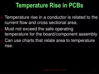
Temperature Rise in PCBs. Temperature rise in a conductor is related to the current flow and cross sectional area. Must not exceed the safe operating temperature for the board/component assembly Can use charts that relate area to temperature rise. Temperature Rise in PCBs.

E N D
Temperature Rise in PCBs • Temperature rise in a conductor is related to the current flow and cross sectional area. • Must not exceed the safe operating temperature for the board/component assembly • Can use charts that relate area to temperature rise. Temperature Rise in PCBs
Temperature Rise in PCBs • Thickness of copper is the original sheet thickness plus the added amount due to plating operations. Temperature Rise in PCBs
Relate temperature rise to current to get area of copper Temperature Rise in PCBs
Knowing total thickness and area can use chart to obtain the width. Temperature Rise in PCBs
Profile of trace will not be regular Temperature Rise in PCBs
Charts were produced in early 60s by the US National Bureau of Standards. • Assumed smaller component areas compared with copper area. • Did not take into account effects of dielectric thickness and material. Thermo-conductive materials have much great cooling effects. • Assumed two layer boards only – much greater cooling with multi-layer boards Temperature Rise in PCBs
Current charts • NBS (National Bureau of Standards) Report #4283 “Characterization of metal-insulator laminates”, D.S. Hoynes, May 1, 1956. Commissioned by Navy Bureau of Ships • The charts are based on double sided material • Formalized in Mil-Std-275 • At this time internal charts were created using 50% of external currents without empirical data. Incorporated into IPC 2221 • Perry Initiative, 1994, IPC-D-275 • Caused 2221 to be split into two standards 2221 and 2222 Temperature Rise in PCBs
Current DT (C) Current (amps) 10 sq.mils Int, 2oz, 70 mil, polyimide Temperature Rise in PCBs
Substrate Thickness DT (C) PCB Thickness (mils) 10 sq.mils Int, 2oz, 70 mil, polyimide Temperature Rise in PCBs
Substrate Material Current (amps) OFF THE SCALE! DT (C) Thermally Conductive Board Material Material Temperature Rise in PCBs
Copper Planes OFF THE SCALE! DT (C) 3.22 sq.mils, vacuum, 1oz trace and 2 oz plane, Int with 1 amp with .005 dielectric space Temperature Rise in PCBs
Copper Planes OFF THE SCALE! DT (C) 3.22 sq.mils, vacuum, 1oz trace and 2 oz plane, Int with 1 amp with .005 dielectric space Temperature Rise in PCBs
The new IPC standard is scheduled to be released later in 2003 IPC-2152 Standard for Determining Current Carrying Capacity in Printed Board Design This has more accurate charts than 2221 Temperature Rise in PCBs
What do you use now? Best tool to use now is the software from Thermal Man: http://www.thermalman.com/about.shtml Has free demo available Temperature Rise in PCBs