Download
1 / 25
250 likes | 515 Vues
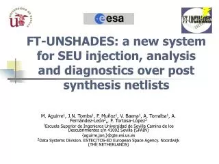
FT-UNSHADES Analysis of SEU effects in Digital Designs for Space. Gioacchino Giovanni Lucia TEC-EDM, MPD - 8 th March Gioacchino.lucia@esa.int Phone: +31 71 5658482. AGENDA. FAULT INJECTION SYSTEM Requirements Classification FT-UNSHADES Tool Features Architecture Software toolbox

E N D
FT-UNSHADESAnalysis of SEU effects in Digital Designs for Space Gioacchino Giovanni Lucia TEC-EDM, MPD - 8th March Gioacchino.lucia@esa.int Phone: +31 71 5658482
AGENDA • FAULT INJECTION SYSTEM • Requirements • Classification • FT-UNSHADES Tool • Features • Architecture • Software toolbox • Test Flow • FPGA TARGET • ASIC TARGET • Case of Study • LEON Processor • Conclusions
REQUIREMENTS FAULT INJECTION SYSTEM • provide information about the behaviour of the circuit when a fault is injected while a given set of stimuli is applied to the circuit • determine the coverage of error detection and recovery mechanisms • evaluate the effectiveness of fault tolerance mechanism • evaluate performance loss • The fault model we refer to is the single transient bit-flip • The bit-flip can be random or deterministic in time and in space, depending on the test objectives • The input stimuli to be used during the analysis process are already available, and we do not deal with their generation or evaluation
CLASSIFICATION • Type of SEU emulated • SEUs may alter the memory elements the design embeds • SEUs may alter the content of the memory storing the device configuration • Type of fault detected • Latent • Damage • Test level • Software • Hardware • Cost • Effort needed to prepare the design for testing • Rent facilities • Level of intrusiveness • Level of information extracted • Speed
AGENDA • FAULT INJECTION SYSTEMS • Requirements • Classification • FT-UNSHADES Tool • Features • Architecture • Software toolbox • Test Flow • FPGA TARGET • ASIC TARGET • Case of Study • LEON Processor • Conclusions
FT-UNSHADES • Developed by University of Sevilla • Emulates SEU in user’s FFs. • Hardware platform • Xilinx Virtex-II FPGA • The capture and readback mechanism • The FPGA configuration memory can be partially read and written. • No Intrusive technique • Easy to use flow • Deep analysis What FT-UNSHADES is not: • It’s not a platform for radiation testing of FPGAs • It’s not designed for being inserted into a radiation environment
Links: • Configuration • Clock Generation • Debug Lines • General I/O • Communication: • 1.5MB/s (USB / EPP) • Multi-Board • Software: • Design preparation • Board handling • Test definition • Analysis ARCHITECTURE • A Xilinx Virtex II called the System FPGA (S-FPGA) is used for the core emulation. • A second FPGA (C-FPGA) is used as an extremely fast bridge between the SW and the S-FPGA. • Large static memories are used to hold up to 2 million input test vectors, each 102 bits wide which are used to stimulate the design MUT.
DESIGN PREPARATIONTARGET: FPGA Test Vector Generation MUT Generation DTE Generation
DESIGN PREPARATION TARGET: ASIC (1/2) • TYPICAL SCENARIO: • SEU radiation tests showed up functional anomalies of a submodule in a large ASIC netlist. • The design size doesn’t allow to test the whole design with FT-U • AIM: • find out the causes of that functional anomalies • What do we need to do? • Extract the module from the netlist so that the size of the design fits in FT-U • FT-U flow requires a VHDL testbech for the test vectors generation so we need to extract the stimuli usually from the system testbench • USE VCD format to dump the input of the DUT. • Write a VHDL testbench which parses the VCD file and feeds the DUT
DESIGN PREPARATION TARGET: ASIC (2/2) • What do we need to do? • Reliable technology remapping of the ASIC netlist to the XILINX library CRITICAL POINT!!! • it must be verified that the translated netlist maintains the exact same sequential logic (FF replication or elimination must be avoided) and 100% functional equivalency (some timing differences may be expected). USE A FORMAL VERIFICATION TOOL! (e.g. Formality) • Build a simulation with the “old” and “new” netlist and compare the outputs to verify the behaviour is the same!! • FT-U can handle up to 102 input pins Wrapper needed
TEST CAMPAIGN DEFINITION and … • Configure the System FPGA and download the test vector database, define some environment variables. • Specify the analysis type: • DAMAGE • LATENT • Specify SEU time constrain • Specify SEU location constrain • Specify number of RUN to perform • RUN: Complete simulation from the first to the last test vector • Specify number of SEU per RUN to inject.
… EXECUTION CLOCK: 133937 REGISTER:leon0_mcore0_proc0_cx S-FPGA GO! STOP 1) Read FF state, write NOT (FF state) 1) IF time counter equal to fault insertion cycle freeze MUT 3) Resume CLK, if(I/O discrepancy is true) read counter; read I/O; classify fault as damage;
AGENDA • FAULT INJECTION SYSTEMS • Requirements • Classification • FT-UNSHADES Tool • Features • Architecture • Software toolbox • Test Flow • FPGA TARGET • ASIC TARGET • Case of Study • LEON Processor • Conclusions
CASE OF STUDY: LEON Processor: • 32 Register windows • 2K I-Cache and D-Cache • No FPU neither coprocessor Peripherals: • Debug Support Unit • 32KB AHB RAM • 2 UARTs + Parallel I/O port • 1 Interrupt Controller • 2 Timers + Watchdog
LEON:TEST CAMPAIGN DEFINITION and EXECUTION • How many runs ? 1, 10, 100, 100K ? • Depends on the number of registers • Depends on the test bench used • What kind of Injection? Random, single register, at a given time…? • It depends on what are you testing • When to stop the test campaign? • When I have all the information I was looking for
LEON: REGISTERS DISTRIBUTION Total: 2559 registers
LEON: INJECTIONS DISTRIBUTION Test Conditions RUNs: 10000 1 SEU x RUN RANDOM UNIFORMDISTRIBUTION
TB_FULL: 18% TB_FUNC_32: 6% Test Condition RUNs: 10000 1 SEU x RUN RANDOM TESTBENCHSEU COVERAGE TO BE EXHAUSTIVE: # CLK CYCLES = 369848 # FLIP-FLOP = 2559 Average time per RUN (s)= 0.26 NEEDED RUNs: 946441032 2848 days!!!
ERRORS vs Injections Distribution Errors Distribution TIMERS: 6% of the Design FFs (127) 565 injections Only 3 ERRORS detected Injections Distribution
NORMALIZEDSENSITIVITY 1.4% of errors Insensitive 74 Registers 87% of errors Very sensitive Only 8 Registers IT’S POSSIBLE TO IDENTIFY WHICH PARTS OF THE DESIGN ARE “MORE SENSITIVE TO SEUs” Average: 20 injections per register
Error Detected After one clock cycle Fault Inj. CLK AND MORE … CLOCK: 133937 REGISTER:leon0_mcore0_proc0_cx.c0_icache0_r.waddress_16 DAMAGE DETECTED: YES LATENCY: 1 CLK PORT: address A step by step analysis can be done, dump the data in VCD format and visualize the fault evolution with a waveform viewer
NEXT STEPS • NEW DESIGNS TO TEST • PCI interface of the AT697E • SpW CODEC/Router • CTM (CCSDS Time Manager) • Unprotected • XTMR_V1 • XTMR_V2 (to be produced) • LEON with specific testbenches aiming to reach a higher coverage.
Conclusions (1/2) • A tool for verification of the design protections • Automatic search of weak/unprotected points in your design BEFOREplace and route and fabrication • Identify which areas are more sensitive in the design (selective protection) • Understand/reproduce rad test results • Verify the correctness of a new implementation of a fault tolerance mechanism
Conclusions (2/2) Factors affecting the probability of detecting “SEU sensitivity” or “SEU protection errors”: • “quality” of the test bench to expose SEU effects. This can be quantified by FT-U • How exhaustive the test campaign is (how many possible SEU cases are covered) • “Faulty SEU protections” can have different probabilities of being detected by an FT-U test