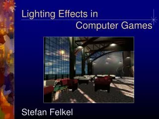
Lighting for Games
Lighting for Games. Kenneth L. Hurley. Agenda. Introduction to Lighting What is Radiosity? Lightmaps Per Pixel Lighting High Dynamic Range Images Low Dynamic Range Image BRDFS. Introduction to Lighting. Ambient Lighting I = Ia x Ka. Introduction to Lighting. Diffuse Lighting

Lighting for Games
E N D
Presentation Transcript
Lighting for Games Kenneth L. Hurley
Agenda • Introduction to Lighting • What is Radiosity? • Lightmaps • Per Pixel Lighting • High Dynamic Range Images • Low Dynamic Range Image • BRDFS
Introduction to Lighting • Ambient Lighting • I = Ia x Ka
Introduction to Lighting • Diffuse Lighting • Ip x Kd x (N . L)
Introduction to Lighting • Phong Shading • Ks x (R . V)^n) • Reflection Calculation • R = (2 x N x (N . L)) - L
Radiosity • What is Radiosity • Objects reflect light at different wave length • Can create a scattered lighting effect • Lightmaps are determined from radiosity solutions • Ray tracing with diffuse reflection calculations usually used to determine radiosity
Lightmaps • Encodes a Diffuse Lighting Solution inSeparate Texture • Think of an interior building wall • Brick surface pattern on walls may be common to many walls and highly repeated • Diffuse lighting solution is different for each wall, but typically low resolution • Light maps decouple surface texture from diffuse lighting contribution • http://hcsoftware.sourceforge.net/RadiosGL/RadiosGL.html
Lightmaps in Quake2 (modulate) decal only lightmaps only = combined scene
Gloss Map Example = + (modulate) Diffuselighting contribution (per-vertex lighting) Gloss maptexture Specularlightingcontribution (per-vertexlighting) Final combined result
Per Pixel Lighting Overview • Introduction to per-pixel lighting • Normal maps • How to create them • Tangent or “surface-local” space • Why we need it • How to use it • Things to watch out for • Animation & Other Topics
Per-Pixel Lighting • Per-Pixel lighting is the next leap in visual quality after simple multi-texturing • It allows more apparent surface detail than would be possible with triangles alone • DX7 HW with DOT3 was a huge leap in per-pixel capability • DX8 HW increases performance again, and adds completely new capabilities
Examples Simple geometry, high detail Reflective bumps A single quad lit per-pixel
Per-Pixel Lighting / Bump Mapping • Bump Mapping is a subset of Per-Pixel Lighting • These slides will discuss them interchangeably • Most older Bump Mapping examples were only performing diffuse directional lighting • Bump Mapping / Per-Pixel Lighting can be used to achieve diffuse and/or specular point lights, spotlights and volumetric lights also
Normal Maps are Bump Maps • Height maps are popular (3DS Max, Maya, ..) • Normal maps are better Normal Map Height Map
Creating Normal Maps • Normal maps are easy to create from height maps • Find slope along each axis: dHeight/dU, dHeight/dV • Cross product of slopes gives normal vector • Convert normal vector (X,Y,Z) [-1,1] to R,G,B color [0,1] • X R, Y G, Z B • Z is “up” out of the image plane • RGB = ( 0.5, 0.5, 1.0 ) corresponds to XYZ = ( 0, 0, 1 ) • XYZ = ( 0, -1, 0 ) RGB = ( 0.5, 0.0, 0.5 ) • Surface normals mostly point up out of the bump map plane, so normal maps are mostly blue simulated surface
C Surface Normal A B D Z U V Creating Normal Maps From Height Maps • Simplest: Use 4 nearest neighbors • dz/du = ( B.z - A.z ) / 2.0f // U gradient • dz/dv = ( D.z - C.z ) / 2.0f // V gradient • Normal = Normalize( (dz/du) (dz/dv) ) denotes cross-product C A B D
Creating Normal Maps From Height Maps • Make sure your height map uses the full range of gray values • Get smoother results by sampling a larger area around each point • 3x3, 5x5, … • NVIDIA provides three tools: • Normal Map Generation Tool (best sampling) • BumpMaker (simple 2-neighbor sampling) • Photoshop plug-in
Creating Normal Maps From Geometry • More esoteric approach • Can be done in a DCC app • Model surface detail in 3D • Create detail up from a flat surface • Render surface with red, green, and blue directional lights, one color for each 3D axis • Need negative lights as well as positive • Orthographic projection
Creating Normal Maps From Geometry • 5 lights, positive & negative • Ambient = ( ½ , ½ , ½ ) +B -R +G +R -G
Normal Map Applied to Geometry • We now have a normal vector for each pixel of the object • Use the normal in standard N • L + N • H lighting eqn. • Normal map vector is relative to the flat triangle it is on. It is NOT a normal in world or object space! • N • L must have Normal and Light Vector in the same coordinate system!
The Light Vector • With vertex lighting, we had • Normal vector per vertex • Light vector per vertex • So far, we’ve got • Normal vector per pixel • We need a light vector for every pixel! • Start with vector to light at each vertex • HW iterates that vector across each triangle • Iterated color or texture coordinate
Interpolated Vector -- Watch Out! • We’re interpolating between vectors linearly • Interpolated vector is not normalized • It can be shorter than unit length • Only noticeable when light is close to object not normalized normalized normalized
Solution – Re-Normalize the Vector • Do this only if you have to • Only if distance from tri to light is less than longest edge of tri, or some other metric • What if you don’t? • Highlights are dimmer • Rare cases you will notice a darkening near the light • Use normalization cube map • Pixel Shaders: Use one step of Newton-Raphson technique to re-normalize • Developed by Scott Cutler at NVIDIA
+V,+Y +Y face +U,+X -X face +X face - Z face +Z face -W-Z -Y face Normalization Cube Map • Access cube map with un-normalized vector (U,V,W) • Result is RGB normalized vector in same direction • Input ( 0, 0, 0.8 ) RGB ( 127, 127, 255 ) which is a normalized vector for per-pixel lighting
Normalization Cube Map • Cube map doesn’t need to be huge • 32x32x8 • 64x64x16 • www.nvidia.com/Developer • “Simple Dotproduct3 Bump Mapping” demo
Newton-Raphson Re-Normalization • One step of numerical technique for normalizing a vector • DX8 Pixel Shaders (or OGL Register Combiners) • Faster than cube normalization map • Numerical method: Normalize( V ) V / 2 * ( 3 - V • V ) when V is close to unit length • Great when angle between interpolated vectors of a tri is no more than about 40º • That’s a big difference, so this is valid for most models & circumstances
Newton-Raphson in DX8 • Approximate V / 2 * ( 3 - V • V ) • V/2 * (3 – V•V) = 1.5V – 0.5V * (V•V) = V + 0.5V – 0.5V * (V•V) = V + 0.5V * ( 1 – ( V • V ) ) • Pixel Shader code: V = t0 vector def c0, 0.5, 0.5, 0.5, 0.5 mul r0, t0, c0 // 0.5 * V dp3 r1, t0, t0 // V DOT V mad r0, 1-r1, r0, t0
N • L Per-Pixel • Can visualize light vector x,y,z as an RGB color • Same [-1,1] [0,1] conversion as for the normal vector Light Vector, L Normal map Per-Pixel Lighting • = = •
What Coordinate System? • Normal vector is expressed relative to each triangle • This is “surface-local” space, aka. “texture space” • It’s a 3D basis, consisting of three axis vectors • S, T, S T ( = cross product ) • Texture space depends on • Geometric position of vertices • U,V coordinates of vertices which determine how the normal map is applied T SxT T SxT S S
How to Calculate Texture Space • NVIDIA sample code! • D3DX utility library for DX8.1 will do it for you! • If you must know… • For each tri, find derivatives of U and V texture coordinates with respect to X,Y, and Z • S vector = dU/dX, dU/dY, dU/dZ • T vector = dV/dX, dV/dY, dV/dZ • Then take S T • Now we have S, T, ST texture space basis for each triangle • S, T, ST is a transform from Object Space into Texture Space
SxT SxT T T S S SxT SxT T T S Resultant Texture Space • Express texture space per-vertex • For each vertex’s S vector, average the S vectors of the tris it belongs to • Same for T and ST vectors • Analogous to computing vertex normals from face normals! S
Add It to Your Geometry • Add S, T, ST vectors to your vertex format (FVF) • We can now transform the object space Light Vector into texture space • This puts L in the same space as our normal map vectors, so N • L lighting will work • DX7: Must transform light vector in SW • Stuff it into Diffuse or Specular color for iteration • or a 3D texture coord for Normalization Cube Map • DX8: Use a Vertex Shader to transform light vector at each vertex • Put it into a color or texture coord for iteration
DX7 vs. DX8 Hardware Implementation • DX7 hardware • Write light vector to a color for iteration • TextureStageState setup example: COLORARG0 D3DTA_DIFFUSE // light vec COLORARG1 D3DTA_TEXTURE // normal map COLOROP D3DTOP_DOTPRODUCT3 • DX8 hardware • Write light vector to a texture coord for iteration • Various Pixel Shader program approaches: tex t0 // normal map texcoord t1 // light vector DP3 r0, t0_bx2, t1 // expand unsigned vals
GeForce I, II Details • Remember: Under DX8, GeForce I & II have a new temporary result register • Also new triadic ops & 3rd argument: D3DTOP_MULTIPLYADD, D3DTOP_LERP • VertexBuffer->Lock(); Write light vector to color or texture coord; VertexBuffer->Unlock() • N • L * BaseTexture 0, COLORARG0 D3DTA_DIFFUSE // light vec 0, COLORARG1 D3DTA_TEXTURE // normal map 0, COLOROP D3DTOP_DOTPRODUCT3 1, COLORARG0 D3DTA_CURRENT // dot3 result 1, COLORARG1 D3DTA_TEXTURE // base tex 1, COLOROP D3DTOP_MODULATE
GeForce 3 Approach • FVF = { pos, nrm, diffuse, t0, S, T, SxT } • Declare vertex shader: S v4; Tv5; SxTv6 • SetVertexShaderConst( C_L, vLightPosObjSpace..) vs.1.1 dp3 oD1.x, v4, c[C_L] dp3 oD1.y, v5, c[C_L] dp3 oD1.z, v6, c[C_L] mov oD1.w, c[CV_ONE] ps.1.1 tex t0 // base tex t1 // normal map dp3 r0, t1_bx2, v1_bx2 mul r0, r0, t0 // plenty of slots left if you // want to do normalization
Animation Keyframe: • Don’t blend between radically different keys • Interpolate S, T, ST & re-normalize (VShader) Matrix Palette Skinning: • Animate S, T, ST vectors with the same transform as for the normal vector • Vertex Shader program makes this trivial • Try using the vertex Normal in place of ST if you need room
Final Bump Map Thoughts • Once you have texture space, you’re all set for many other effects • Normal maps can be created and modified on the fly very quickly with DX8 hardware! • Normal Map + Detail Normal Map for added detail • Similar to texture + detail texture • Per-pixel lighting adds tremendous detail
High Dynamic Range Images • Developed by Paul E. Debevec and Jitendra Malik • http://www.debevec.org • Radiance can vary beyond precision of 8 bits • Encodes radiance in floating point values • Demo at site uses Geforce2 • Commercial Licensing Required
Low Dynamic Range Images • Simply lighting encoded in cubemap • Low precision but can be effective for Diffuse lighting • Take high resolution photographs of mirrored ball from as many as 6 angles
Low Dynamic Range Images • Align images into cubemap faces.
Low Dynamic Range Images • Run though diffuse convolution filter
Low Dynamic Range Images • Results
BRDFS • Principals of BRDF Lighting
What is a BRDF? observer light N L θL θV V • BRDF Stands for Bi-directional Reflectance Distribution Function • BRDF is a function of incoming light direction and outgoing view direction surface • In 3D, a direction D can be represented in spherical coordinates (D, D) • A BRDF is a 4D function: BRDF( L, L, V, V )
Multi-Texture BRDF Approximations • Basic Idea: • Approximate the 4D function with lower dimensional functions • “Separate” the BRDF into products of simpler functions • BRDF(L,V) G1(L)*H1(V) + G2(L)*H2(V) + … • Minnaert Reflections are a little easier • Only encodes (L * N) and (V * N)
References • Computer Graphics at University of Leeds, http://www.comp.leeds.ac.uk/cuddles/hyperbks/Rendering/index.html • Paul E. Debevec and Jitendra Malik. Recovering High Dynamic Range Radiance Maps from Photographs. In SIGGRAPH 97, August 1997.
Questions… ? www.nvidia.com/Developer