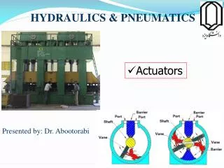
Basic Hydraulics and Pneumatics
Module 1: Introduction to Hydraulics. Basic Hydraulics and Pneumatics. By :Samir Hamasha. Module 1: Introduction to Hydraulics. Module Objectives After the completion of this module, the student will be able to: Identify the common uses of hydraulic systems.

Basic Hydraulics and Pneumatics
E N D
Presentation Transcript
Module 1: Introduction to Hydraulics Basic Hydraulics and Pneumatics By :Samir Hamasha
Module 1: Introduction to Hydraulics • Module Objectives After the completion of this module, the student will be able to: • Identify the common uses of hydraulic systems. • Determine that liquids are incompressible. • Identify the fundamental parts of a hydraulic system. • Observe how hydraulic components can be connected together to construct a hydraulic circuit. • Identify the main components of the hydraulic work station TP 501. • Explain the main parts of the hydraulic power pack. • Explain the importance of using standard hydraulic symbols. • Identify the basic hydraulic laws. • Calculate the piston area, force, and pressure. • Explain Pascal’s law and apply it on different examples. • Differentiate between the flow rate and flow velocity. • Demonstrate the continuity equation. • Calculate the area, velocity, and flow rate at different sections of a pipe. • Describe how to read a pressure gauge in the US and SI units. • Set the pressure gauge of the hydraulic power pack to a certain pressure.
Module 1: Introduction to Hydraulics All machines require some type of power source and a way of transmitting this power to the point of operation. The three methods of transmitting power are: • Mechanical • Electrical • Fluid • In this course we are going to deal with the third type of power transmission which is the Fluid Power
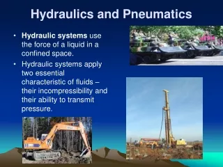
Module 1: Introduction to Hydraulics • Fluid power is the method of using pressurized fluid to transmit energy. • Liquid or Gas is referred to as a fluid. Accordingly, there are two branches of fluid power;Pneumatics, and Hydraulics. • Hydraulic systems use liquid to transfer force from one point to another. • Pneumatic systems use air to transfer force from one point to another. Air is
Module 1: Introduction to Hydraulics • Air is Compressible: (This describes whether it is possible to force an object into a smaller space than it normally occupies. For example, a sponge is compressible because it can be squeezed into a smaller size). • liquid is Incompressible: (The opposite to compressible. When a “squeezing” force is applied to an object, it does not change to a smaller size. Liquid, for example hydraulic fluid, possesses this physical property).
Module 1: Introduction to Hydraulics • Hydraulic systems are commonly used where mechanisms require large forces and precise control. • Examples include vehicle power steering and brakes, hydraulic jacks and heavy earth moving machines.
2.Uses of hydraulics • Hydraulics plays an important role in many industries; there are a lot of hydraulic applications in manufacturing, transportation, and construction sectors. • Hydraulics systems are used where large, precise forces are required.
2.1 Common examples of hydraulic systems include: 2.1.1 Vehicle brake hydraulic systems The function of a vehicle braking system is to stop or slow down a moving vehicle. When the brake pedal is pressed as illustrated in Fig. 1.1, the hydraulic pressure is transmitted to the piston in the brake caliper of the brakes. The pressure forces the brake pads against the brake rotor, which is rotating with the wheel. The friction between the brake pad and the rotor causes the wheel to slow down and then stop. Tip: Watch the hydraulic brake system video. Fig.1.1: A schematic diagram of the vehicle’s hydraulic brake system.
2.1 Common examples of hydraulic systems include: 2.1.2 Vehicle power steering • The vehicle power steering system uses hydraulic oil, the hydraulic pump supplies the oil through the control valves to the power cylinder as shown in Fig. 1.2. The major advantage of using this system is to turn the vehicle’s wheels with less effort. Fig.1.2:Vehicle hydraulic power steering system
2.1 Common examples of hydraulic systems include: 2.1.3 Hydraulic jack • In a hydraulic jack, a small piston (pumping piston) transmits pressure through the oil to a large piston (power piston) through a check valve, resulting in the weight being lifted as shown in Fig.1.3. • Tip: Watch the hydraulic jack video. (a) Hydraulic jack (b) Hydraulic jack schematic diagram
2.1 Common examples of hydraulic systems include: 2.1.4 Aircraft hydraulic systems • All modern aircraft contain hydraulic systems to operate mechanisms, such as: • Flaps (Fig. 1.4a) • Landing gear (Fig. 1.4a) • The hydraulic pump that is coupled to the engine provides hydraulic power as illustrated by Fig. 1.4b. • Power is also distributed to systems through the aircraft by transmission lines. • Hydraulic power is converted to mechanical power by means of an actuating cylinder or hydraulic motor. (a) Landing gears and flaps (b) Landing gear schematic diagram
3 Hydraulic system components • All industrial hydraulic systems consist of the following basic components • Power input device: The pump and motor together are called the power input device; the pump provides power to the hydraulic system by pumping oil from the reservoir/tank. The pump’s shaft is rotated by an external force which is most often an electric motor as illustrated in Fig 1.5.
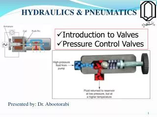
3 Hydraulic system components • Control device: Valves control the direction, pressure, and flow of the hydraulic fluid from the pump to the actuator/cylinder. • Power output device: The hydraulic power is converted to mechanical power inside the power output device. The output device can be either a cylinder which produces linear motion or a motor which produces rotary motion. • Liquid: the liquid is the medium used in hydraulic systems to transmit power. The liquid is typically oil, and it is stored in a tank or reservoir. • Conductors: The conductors are the pipes or hoses needed to transmit the oil between the hydraulic components.
3.1 Hydraulic power pack • The hydraulic power pack combines the pump, the motor, and the tank. The hydraulic power pack unit provides the energy required for the hydraulic system. The parts of the hydraulic power pack unit are shown in Fig. 1.6. .1.6: The main parts of the hydraulic power pack
3.2 Activity 1: Hydraulic station component identification • In this activity, you will identify the components of the Festo Hydraulic work station in your lab: • Locate the power pack unit and identify its parts. • Locate the out put device (actuators). • Locate the control devices (valves). • Locate the conductors (hoses).
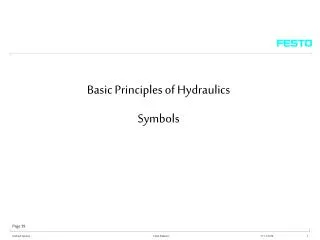
3.3 Hydraulic symbols • The way hydraulic components direct and control liquid around a circuit can be complex. • This would cause difficulty for one engineer explaining to another engineer how the circuit works. • A common form of representing components and circuits is used to more easily explain what is happening. • This form of representation uses common symbols to represent components and the ways in which they are connected to form circuits. Fig. 1.7 shows some of the components’ symbols used in hydraulics. • The symbols don’t show the component construction, or size, however, it is a standard form that is used by all engineers to represent that specific component. (a) Electric motor (b) Hydraulic pump (c) Tank or reservoir (d)Pressure relief valve Fig.1.7: (a) Electric motor. (b) Hydraulic pump. (c) Tank or reservoir. (d) Pressure relief valve.
Power Pack Symbols • The simplified and detailed symbols of the hydraulic power pack are shown in Fig. 1.8. (a) Simplified (b) Detailed Fig.1.8: (a) Simplified symbol of the hydraulic power pack. (b) Detailed symbol of the hydraulic power pack.
4- Fundamental laws of Hydraulics • All hydraulic systems operate following a defined relationship between area, force and pressure. • Laws have been established to explain the behavior of hydraulic systems. • Hydraulic systems use the ability of a fluid to distribute an applied force to a desired location.
4- Fundamental laws of Hydraulics4.1 Pressure • When a force (F) is applied on an area (A) of an enclosed liquid, a pressure (P) is produced as shown in Fig. • Pressure is the distribution of a given force over a certain area. • Pressure can be quoted in bar,pounds per square inch (PSI) or Pascal (Pa) .
4.1 Pressure • Where • Force is in newtons (N) and • Area is in square meters (m2). • 1 Pascal (Pa) =1 N/m2. • 1 bar= 100,000 Pa= 105 Pa. • 10 bar= 1 MPa (mega Pascals)
4.1 Pressure • If the pressure is calculated using a force in Newton, and area in square millimeters, the pressure in bar can be calculated. Example 1-1. A cylinder is supplied with 100 bar pressure; its effective piston surface is equal to 700 mm2. Find the maximum force which can be attained. • P= 100 bar = 100X100000 N/m2. • A= 700/1000000=0.0007 m2. • F= P.A= 100X100000X0.0007= 7,000 N
4.2 Pascal’s Law • Pascal’s law states that: “The pressure in a confined fluid is transmitted equally to the whole surface of its container” • When force F is exerted on areaA on an enclosed liquid, pressureP is produced. The same pressure applies at every point of the closed system as shown in Fig. 1.10a. Fig.1.10: (a) Pascal’s law.
4.2 Pascal’s Law • Fig.1.10b shows that, if a downward force is applied to piston A, it will be transmitted through the system to piston B. • According to Pascal’s law, the pressure at piston A (P1) equals the pressure at piston B (P2) Fig.1.10: (b)Power transmission
4.2 Pascal’s Law Fluid pressure is measured in terms of the force exerted per unit area. The values F1, A2 can be calculated using the following formula: , and
4.2 Pascal’s Law • Example 1-2. • In Fig.11, find the weight of the car in N, if the area of piston A is 0.0006m2, the area of piston B is 0.0105 m2, and the force applied on piston A is 500 N. • Solution:
4.2 Pascal’s Law • Example 1-3. In Fig 1.11, if the weight of the car is 10,000 N, the diameter of piston A is 0.01 m, and the force applied on piston A is 250 N. Calculate the area of piston B. • Solution: 1. Calculate the area of piston A, the piston shape is circular as shown in Fig. 1.10a, accordingly the area will be calculated using the following formula.
4.2 Pascal’s Law • 2. Apply Pascal’s law • 3. Use Pascal’s law to calculate the area of piston B
4.3 Liquid flow 4.3.1 Flow rate versus flow velocity The flow rate is the volume of fluid that moves through the system in a given period of time. Flow rates determine the speed at which the output device (e.g., a cylinder) will operate. The flow velocity of a fluid is the distance the fluid travels in a given period of time. These two quantities are often confused, so care should be taken to note the distinction. The following equation relates the flow rate and flow velocity of a liquid to the size (area) of the conductors (pipe, tube or hose) through which it flows. Q = V x A Where: Q= flow rate ( m³ /s ) V= flow velocity (m / s ) A= area (m² )
4.3 Liquid flow This is shown graphically in Fig. 1.11. Arrows are used to represent the fluid flow. It is important to note that the area of the pipe or tube being used. Fig.1.11: Flow velocity and flow rate
4.3 Liquid flow • Example 1-4. A fluid flows at a velocity of 2 m/s through a pipe with a diameter of 0.2 m. Determine the flow rate. Solution: 1. Calculate the pipe area 2. Calculate the flow rate
4.3.2 The continuity equation Hydraulic systems commonly have a pump that produces a constant flow rate. If we assume that the fluid is incompressible (oil), this situation is referred to as steady flow. This simply means that whatever volume of fluid flows through one section of the system must also flow through any other section. Fig. 1.12 shows a system where flow is constant and the diameter varies Fig.1.12: Continuity of flow.
4.3.2 The continuity equation The following equation applies in this system: Therefore, The following example illustrates the significance of the continuity equation shown above.
4.3.2 The continuity equation • Example 1-5. • A fluid flows at a velocity of 0.2 m/s at point 1 in the system shown in Fig. 1.12. The diameter at point 1 is 50mm and the diameter at point 2 is 30 mm. Determine the flow velocity at point 2. Also determine the flow rate in m/s. • 1. Calculate the areas
4.3.2 The continuity equation 2. Calculate the velocity at point 2 Therefore, 3. Calculate the flow rate in m/s
4.3.2 The continuity equation The example shows that in a system with a steady flow rate, a reduction in area (pipe size) corresponds to an increase in flow velocity by the same factor. If the pipe diameter increases, the flow velocity is reduced by the same factor. This is an important concept to understand because in an actual hydraulic system, the pipe size changes repeatedly as the fluid flows through hoses, fittings, valves, and other devices.
5 Reading the pressure gauge • The pressure gauge indicates the amount of pressure in a system. Technicians read these gauges to determine if a machine is operating properly. • Most pressure gauges have a face plate that is graduated either in US units (psi) or SI units (Pascal or bar) note that; 1 bar=0.1 mega pascalsas explained
5 Reading the pressure gauge • A pointer rotates on the graduated scale as the pressure changes to indicate the pressure in the system. The pressure gauge used in the hydraulic power pack is shown in Fig. 1.13. The outer black scale indicates pressure units of bar, and the inner red scale indicates pressure units in psi Fig. 1.13: A pressure gauge.
5 Reading the pressure gauge • Each scale is graduated with a series of numbers ranging from 0 to a maximum number. In case of the gauge shown, it is graduated from 0 to a maximum reading of 100 bar or a maximum reading of 1450 psi. The maximum reading is always called the range of the gauge. • To read the pressure gauge, you only need to read the inner red scale or the outer red scale to which the pointer points. If the pointer points to a position between the two numbers, you read the gauge to the closest graduation. • In the bar scale there are 4 graduations between 0 and 20; this means the value of each graduation is 20/4=5 bar. In the psi scale there are 4 graduations between 0 and 200; this means the value of each graduation is 200/4=50 psi.
5.1 Activity 2: Setting the hydraulic pressure to 30 bar. Procedures: 1- Switch on the electrical power supply first and then the hydraulic power pack. 2- Use the pressure relief valve to set the pressure to 30 bars. 3- While you are adjusting the pressure observe the pressure gauge. 4- When the pressure gauge indicates 30 bar, switch off the hydraulic power pack first, and then the electrical power supply For more information, refer to the movie section Fig. 1.13: The hydraulic power pack.