Download
1 / 41
750 likes | 1.77k Vues
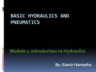
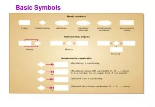
Basic Principles of Hydraulics Symbols. Page 19. Symbols. Pumps. One direction of flow. Constant delivery for constant speed. Fixed Displacement. One direction of flow. Variable delivery for constant speed. Variable Displacement. Pressure compensated variable pump

E N D
Basic Principles of Hydraulics Symbols Page 19
Symbols Pumps One direction of flow. Constant delivery for constant speed Fixed Displacement One direction of flow. Variable delivery for constant speed Variable Displacement Pressure compensated variable pump One direction of flow, adjustable spring and pump case drain. Method of adjustment is shown on the arrow Directional of flow reversible. Variable delivery for constant speed. Hydraulic Energy Source (simplified representation) Page 21
M M Symbols Drive units Electric Motor Engine Motors One direction of rotation. Constant shaft speed for constant flow rate Fixed Displacement Either direction of rotation, depending on direction of flow. Constant shaft speed for constant flow rate. Either direction of rotation. Speed variable for constant flow. Variable Displacement Page 22
x y Symbols Semi rotary actuator Limited rotary movement eg 1800 Pressure Intensifiers Equipment to transform a pressure x in to a pressure y Single acting Continuous Page 22
Symbols Actuators Single Acting Returned by external force Spring return Vent Telescopic Cylinder Page 23
Symbols Actuators Forward and return stroke under power Single piston rod. Double acting Double ended piston rod Double acting Variable cushioning at both ends. Cushioned Page 23
Symbols Directional Control Valves A P 2/2 way valve Normally closed Two Way Porting (2 position) A P T 3/2 way valve Normally closed Three Way A B P T 4/2 way valve Changeover Four Way Page 24
Valve Description 3 Number of Ports Page 24
Valve Description 3 Number of Ports Number of Control positions Page 24
Valve Description 3 Number of Ports Number of Control positions 2 (Number of Boxes) Page 24
Valve Description 3 Number of Ports Number of Control positions 2 (Number of Boxes) Push Button Method of Operation Page 24
Valve Description 3 Number of Ports Number of Control positions 2 (Number of Boxes) Push Button Method of Operation Spring Method of Return Page 24
Valve Description 3 Number of Ports Number of Control positions 2 (Number of Boxes) Push Button Method of Operation Flow path blocked when valve is at rest Spring Method of Return Normally Closed Normally closed Flow path open when valve is at rest or Normally open Page 24
A B P T A B P T A B P T Symbols Directional Control Valves Closed centre 3 position valves Open centre Tandem centre Page 25
A B P T A B P T Symbols Directional Control Valves 3 position valves Floating Centre Regenerative Centre Page 25
Symbols General manual operation Usually used to represent a manual override Methods of Operation Lever operation Foot Pedal operation Push Button operation Detent operation Usually used with lever operation Page 26
Symbols Methods of Operation Pilot operation Roller operation Spring operation Usually used as a return or centring function Solenoid operation Internal pilot or 2 stage operation Usually used with solenoid operation Page 26
Symbols Non return valves Opens if inlet pressure is higher than outlet pressure Free Spring loaded Opens if inlet pressure is higher than outlet pressure plus spring load Can be opened to permit reverse flow by means of pilot pressure Pilot operated Page 27
Symbols Pressure Controls Single stage with internal drain Pressure Relief Valve Also sometimes represented so With external drain Page 28
Symbols Pressure Controls Pressure Relief Valve Remote pilot control with internal drain Internally piloted or 2 stage relief valve Page 28
Symbols Pressure Controls A Pressure Regulating Valves Downstream pressure control Forward flow only external drain B Downstream pressure control. If outlet pressure exceeds set pressure, flow is diverted to tank. 3 way pressure regulating valve Page 29
Symbols Pressure Controls Pressure regulator with reverse flow by-pass built in Page 29
A B Symbols Comparison Pressure Controls Pressure Relief Pressure Regulator Pressure operation from inlet Pressure operation from outlet Shown normally open Shown normally closed Valve is closed until the pressure at the inlet is high enough to open it (set pressure). Flow is then usually to tank. Valve is open until the pressure at the outlet is high enough to close it (set pressure). Flow is usually to cylinder or other part of the circuit.
Symbols Pressure Controls Maintains upstream pressure, allows flow through to other functions. Sequence Valves Maintains upstream pressure, allows flow through to other functions. External drain Two stage sequence valve Provides controlled backpressure for load support. With built in by-pass Counterbalance valve Page 30
Symbols Flow Controls Flow proportional to preset area times the square root of the pressure drop across restrictor Non pressure compensated Flow restricted in one direction only. Page 31
Symbols Flow Controls Flow proportional to preset area irrespective of valve pressure drop. Direction of flow as indicated (non reversible). Excess flow must find alternative path. Pressure Compensated Also sometimes Pressure & Temperature Compensated Preset area automatically adjusts to compensate for viscosity changes Bypass Regulator Excess flow bypassed internally Page 31
Symbols Flow Controls Input flow is divided to 2 flows of fixed ratio Pressure compensated. Flow divider Page 31
Symbols Proportional Valves Valve with 2 distinct operating positions, fully open and fully closed, and an infinite number of intermediate positions. 4/3 directional control valve, proportional. 3 distinct operating positions with closed centre position and an infinite number of intermediate positions. Solenoid current is controlled through proportional amplifier. Servo valve Controlled by a torque motor. Direction of movement is dependent on voltage polarity. Amount of movement is dependent on magnitude of current. Page 32
Full flow Flow Rate Spool Travel Symbols Modulating Control Valves More often referred to as Proportional Control Valves and usually solenoid operated. With these valves there is a known relationship between the position of the spool and the flow through the valve. Therefore flow (speed) can be controlled electronically without the need for adjusting manual valves. Proportional Valve Conventional valve
Symbols Miscellaneous Vented to atmosphere Reservoirs Return line below fluid level Return line above fluid level Header tank Page 33
Symbols Miscellaneous Conditioning Units Filter or Strainer Cooler Water cooled Heater Page 33
Symbols Miscellaneous Pressure Gauge Shut off valve Accumulator Gas type Page 34
Hydraulic Formula Force (F) = Area (A) x Pressure (P) Newtons (N) Square metres (sq. m) Pascals (Pa) Pounds (lbf) Square inches (sq. in) Pounds/sq.in (psi) Note: * The pascal is a very small unit of pressure. 100 Kpa = 10N = 14.5 psi = 1 Bar cm2 e.g. 5000KPa = 50 Bar = 725 psi F = A x P P = F A = F A P ------------------------------------- Page 37
Hydraulic Formula Flow Rate = Flow Velocity x Flow area metres 3 / sec metres / second metres 2 Usually flow rate is given in Litres/minute and flow area given in cm2 or mm2 . Care must be taken to ensure the correct multiples are used. Eg. Calculate the cross sectional area required for the suction line of a pump delivering 40 l/min with a maximum flow velocity of 1.2 m/s. Area = Flow rate40 l/min = 40/60 x 10-3 m3/s Flow velocity Area = 40 x 10-3 m2 60 x 1.2 Area = 0.555 x 10 -3 m2 (Pipe bore of 26.6mm) -------------------------------------------------------------------------- Volume of cylinder (base end) = Piston area x stroke length Volume of cylinder (rod end) = (Piston area - Rod area) x stroke length Page 37
Hydraulic Formula Work done = Force x distance moved Force on a piston = Pressure x area of piston So, work done = Pressure x area x distance moved Area x distance moved = Volume So Work done = Pressure x volume Power is the rate of doing work or, work done per unit of time. Volume per unit time is flow rate - m3/second Page 38
Hydraulic Formula So Hydraulic power = Pressure x Flow rate If pressure is in Pascals (N/m2) and the flow rate is in m3/second then Hydraulic power = Pressure x Flow rate - (Nm/s) = Watts It is usual to give flow rate in litres/minute and pressure in bars. To use these units in the calculation the following conversion has to be made. Hydraulic Power (kW) = Pressure (bar) x Flow rate (l/min) 600 Page 38
1) If a system pressure of 3000 p.s.i acts on a piston area of 3 sq ins, (approx 2 ins diameter) what force will be produced? 2) If a force of 10,000 lb is produced from a cylinder with a piston area of 2.5 sq ins, what is the pressure build up in the system? 3) If a force of 15,000 Newtons is produced in a cylinder with a piston area of 20 sq cm, what is the pressure build up in the system? 4) A cylinder with piston area 150 sq cm and stroke length of 400cm must fully extend in 15 seconds. What flow rate (in Litres/min) must the pump deliver to achieve this? 5) If a hydraulic pump is delivering a flow of 40 litres / min against a pressure of 150 bar, what is the power consumption (in KW) at the pump?