3.0 Theory of Operation
220 likes | 468 Vues
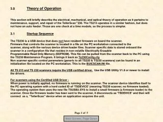
Next Screen, Page Down. 3.0 Theory of Operation This section will briefly describe the electrical, mechanical, and optical theory of operation as it pertains to maintenance, support, and repair of the TellerScan ™ 4120 scanner. 3.1 Startup Sequence

3.0 Theory of Operation
E N D
Presentation Transcript
Next Screen, Page Down 3.0 Theory of Operation This section will briefly describe the electrical, mechanical, and optical theory of operation as it pertains to maintenance, support, and repair of the TellerScan™4120 scanner. 3.1 Startup Sequence The TS4120 is a USB device that does not have resident firmware on board the scanner. Firmware that controls the scanner is located in a file on the PC workstation connected to the scanner along with various device driver/loader files. Scanner specific data is stored onboard the scanner in a configuration file that resides in non-volatile Electrically Erasable Programmable Read Only Memory (EEPROM). Non scanner specific control parameters (generic to all TS4120 scanners) can be found in the Ts2cfg.ini initialization file located on the PC workstation. When power is initially applied, no firmware is running on the scanner. The scanner device identifies itself to the PC operating system with a hard coded ID of TSDevice. When the application program loads, the dynamic link library (dll) determines which operating firmware to download to the scanner, and completes the process automatically. The scanner is now operational. This startup sequence is very quick and can be monitored by observing the power LED indicator on the top cover of the scanner. When power is switched on, the Power On LED illuminates immediately as RED indicating power is on. When the application program is launched and acquires the scanner the Power LED turns GREEN. This signifies that the operating firmware has completed it’s download to the scanner. This process takes approximately 7 seconds. The scanner is now operational, The Amber LED functions as an indication of ‘Check(s) Present in the Hopper’. Page 1 of 16
Next Screen, Page Down 3.2 Check(s) Present Sensor The presence of checks at the feeder entrance is detected by an infrared (IR) sensor placed just slightly above the surface of the Base Plate. This placement is intended to insure that checks are positioned all the way down flat against the base plate prior to pulling them into the scanner track to help eliminate skewed images (see illustrations below). Note: The face of the checks need to be facing outward for proper orientation. Page 2 of 16
Next Screen, Page Down Inner Sensor 3.2 Check(s) Present Sensor(Cont) Page 3 of 16
Next Screen, Page Down Double Feed & Sync Sensors Page 4 of 16
Next Screen, Page Down 3.3 Synchronization/Double Feed Sensor (Cont) Page 5 of 16
New inside separation roller Double Feed Roller Screw Access Hole (on all -22 & -22P units) Next Screen, Page Down Page 6 of 16
Next Screen, Page Down 3.6 Double Feed Sensor The principle of this function is based upon the ability to pass infrared energy through a check to the photo-receptor on the opposite side. By means of software calibration of the circuitry associated with the phototransistor, the opacity of the check can be precisely measured. Two checks (as in a double feed condition) are obviously much more opaque than a single check, and will therefore be detected by the circuitry and indicated as a double feed. The sensors consist of two distinct photo-receptors placed apart from each other. This is to minimize false readings based on special strips or dark areas on the document. Page 7 of 16
Next Screen, Page Down Page 8 of 16
Next Screen, Page Down Page 9 of 16
Next Screen, Page Down Page 10 of 16
Next Screen, Page Down Page 11 of 16
Next Screen, Page Down Magnet MICR Head Page 12 of 16
Next Screen, Page Down Page 13 of 16
Next Screen, Page Down The inkjet carriage assembly is run at a fixed height and prints on the rear side of the document prior to passing by the rear camera. The operating principle is the same as for all the Ink Jet printers. The printer derives its 22VDC power, and is driven by electronics located on the main control board of the scanner. The most significant parameters controlling the printer operation are: a)Print Position, expressed in pixels beginning from the left side of the check b)Print Intensity c)Print Thickness These parameters are selectable and programmable within the API initialization file, and can be configured from the PC. Various parameters in the scanner specific configuration file (located onboard the scanner) control the cleaning intervals, duration, and intensity. The print head is fully under program control. The DCC API offers several options and modes for printing. From a fixed block font to BMP graphical fonts. Page 14 of 16
Next Screen, Page Down Page 15 of 16
Next Screen, Page Down TS4120 Overhead View Ink Jet Platform (Optional) Doc LED Power LED Swing Open Camera Door Auto Feeder – 1 to 100 Items Exit Pocket Diverter Sync & double feed sensor Main Driver Rollers (Inner Pocket) Primary Pocket Page 16 of 16