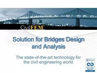
Solution for Bridges Design and Analysis
Solution for Bridges Design and Analysis. The state-of-the-art technology for the civil engineering world. Main Features. Concrete Creep and Shrinkage Bridge layout modeling (in plan and elevation view) Utilities for generating common bridge sections and layout design

Solution for Bridges Design and Analysis
E N D
Presentation Transcript
Solution for Bridges Design and Analysis The state-of-the-art technology for the civil engineering world
Main Features • Concrete Creep and Shrinkage • Bridge layout modeling (in plan and • elevation view) • Utilities for generating common bridge sections and layout design • Geometric and finite element model generation with both Beams (1D) and Solid elements (3D) • Loads Generation • Overloads • Moving loads (vehicle’s editor) • Utility for Prestressing forces input • User loads • Automatic Loads combination • Simulation of the construction process
Concrete Creep and Shrinkage • Effects of Creep and Shrinkage relative to concrete maturity can be easily considered • Allows to obtain the deformed • shape as well as the forces, • moments and stresses in the model
Bridge Layout Modeling • This utility allows to generate the geometry and the finite element model of the bridge from common engineering blueprints. It works as a “layout program”, allowing to define the layout design in both plan and elevation views • The procedure used for the bridge layout definition is the following: • Definition of the mileage points (MP’s) that represent the structure axis • Definition of plan and elevation layout • All the input data to create the layout and their corresponding results can be later retrieved with a single command (~CFGET)
Bridges Layout in Plan View • In plan view, the mileage points line is a succession of user-defined stretches: • straight segments • circular arcs • clothoid arcs
Bridge Layout in Elevation View • In elevation view, the mileage points line is a succession of user-defined stretches: • straight segments • parabolic arcs
Bridge Cross Sections • This module includes a library of typical bridge cross sections, which are defined by the outline of the section: • Slab cross sections • Box cross sections
Slab Concrete Sections • It’s possible to define holes • The sections can be symmetric or asymmetric • Sections and the hole diameters might vary along the bridge
Box Sections with Variable Depth • Any generic box section can be easily defined • All the necessary input parameters can be introduced either by menu or using the corresponding command (allows performing a parametric design of cross sections, creating macros, etc).
Assigning Attributes • For the automatic generation of the geometrical and FEM model, the defined cross sections are assigned to the mileage points (MP’s) forming the bridge layout • The transition of sections between MP’s can be defined using straight segments and splines
Assigning Attributes • The cross sections may have the following attributes: • Offsets • Banks • Skew • Hollow or solid sections
Model Generation • Once the layout and cross sections are defined the geometrical and FEM model generation can be automatically performed by the program
Model Generation • Once the layout and cross sections are defined the geometrical and FEM model generation can be automatically performed by the program
Model Generation • Just by specifying an element type, a Solid finite element model or a Beam finite element model can be generated Solid element model Beam element model (shape option)
Model Generation • From this version on, generation of Box Bridges using SHELL elements is supported
Model Generation • From this version on, generation of Box Bridges using SHELL elements is supported
Model Generation • Allows for a trial and error process using beam elements (less CPU and engineer time). • Automatic discretization of the beam element cross- sections into points and tessella (allows for analyzing the section’s internal behavior using beam elements) • More accurate design can be performed using SOLID elements by only changing the element type and running the analysis again.
Suspension Bridges Wizard Suspension Bridge Generator windows can generate 3D models for: • Concrete Suspension Bridges(with a CivilFEM bridge section) • Steel Suspension Bridges(with a CivilFEM 3D steel truss pattern) • Generic Suspension Bridges(with a CivilFEM generic cross section) • Mixed section, two types of section: - Concrete slab over I-section steel beams - Concrete slab over a steel box section
Suspension Bridges Wizard • By using this Wizard it is possible to easily introduce the number of segments and the corresponding data to generate the entire bridge model for both 3D beams and solid elements.
Suspension Bridges Wizard • Concrete
Suspension Bridges Wizard • Both concrete and steel truss suspension bridge models are automatically generated for any generic configuration by just inputting a few parameters. • Steel
Suspension Bridges Wizard • Steel
Suspension Bridges Wizard • Any generic cross section from library and/or any 2D defined using CivilFEM with ANSYS meshed drawing (capture utility) can be used as a bridge cross section • Optimization of the geometry • and initial tensions of cables
Suspension Bridges Wizard • Mixed Section (type 1) Bridge section is composed of a concrete slab over I-section steel beams:
Suspension Bridges Wizard • Mixed Section (type 1)
Suspension Bridges Wizard • Mixed Section (type 1)
Suspension Bridges Wizard • Mixed Section (type 1) Example
Suspension Bridges Wizard • Mixed Section (type 2) Bridge section is composed of a concrete slab over a steel box section:
Suspension Bridges Wizard • Mixed Section (type 1)
Suspension Bridges Wizard • Mixed Section (type 1)
Suspension Bridges Wizard • Mixed Section (type 2) Example
Supported Bridges Wizard • Same parameters used in suspension bridges are also employed here, but only the bridge deck is generated.
Suspension Bridges Wizard • Supported Bridge Examples
Cable Stayed Bridge Wizard • Generation window
Cable Stayed Bridge Wizard • Model generation • Cable arrangements: HARP TYPE FAN TYPE
Cable Stayed Bridge Wizard • Model generation • Towers: Unlimited in number, variable cross sections, vertical or inclined with multiple cable arrangements
Model Generation Cable Stayed Bridge Wizard • Different boundary conditions and connection between towers and deck
Nonlinear Construction Process Analysis: Cable Stayed Bridge Wizard
Cable Stayed Bridge Wizard • Nonlinear Construction Process Analysis:
Cable Stayed Bridge Wizard • Nonlinear Construction Process Analysis: • Cable force optimization: Deflection
Cable Stayed Bridge Wizard • Nonlinear Construction Process Analysis: • Cable force optimization: Bending Moment
Arch Bridge Wizard • Arch Bridge Generator (Beam Model)
Arch Bridge Wizard • Depending on the position of the bridge deck compared to the arch, there are different cases:
Arch Bridge Wizard • Beam Model
Arch Bridge Wizard • Shell Model
Bridge Components • CivilFEM with ANSYS allows a detailed analysis of piers, cross bracings, diaphragms, etc.
Special Features • Any of the bridge parameters (layout, sections, dimensions, etc.) can be easily parameterized by the user, allowing very fast sensitivity analysis, making use of some advanced features: • Log files • the program stores in a file all the orders executed by the program during a job. This file can be edited by the user at any time and the model can be executed again by just reading it • Macros (APDL) • Customization: users are able to create their own windows, commands, etc, customizing the program as much as possible to their own needs