Download
1 / 19
200 likes | 548 Vues
http:// nanomechsim.technion.ac.il. Technion - Israel Institute of Technology Faculty of Mechanical Engineering The Nanomechanics Simulations Laboratory. Modeling the Strength of Ni 3 Al Nanocubes Using Molecular Dynamics Simulations. By : Koren Shreiber, Msc Guidance : Dr. Dan Mordehai.

E N D
http://nanomechsim.technion.ac.il Technion - Israel Institute of Technology Faculty of Mechanical Engineering The Nanomechanics Simulations Laboratory Modeling the Strength of Ni3Al Nanocubes Using Molecular Dynamics Simulations By: Koren Shreiber, Msc Guidance: Dr. Dan Mordehai
Smaller is Stronger • At the sub-micro meter scale, metal specimens obey different mechanical properties than their bulk counterparts. • Size dependent strength. • MPa compressive stresses with bulk regime, GPa with nano -particles. Bulk regime Mordehai et al.Acta Mater. 59, 2309(2011)
Contents • Background • Ni3Al • Dislocations theory • Experiments • Molecular Dynamics simulation • Research steps • Step 1 – Validate screw dislocation properties in a perfect lattice • Step 2 – Calculate the dissociation widths • Step 3 – Compression of nanoparticles • What’s next?
Ni3Al Lattice Ni3Al alloys are important for technological applications mainlydue to their high strength at elevated temperatures (200-900 [MPa] tensile yield stress). • FCC – Face Centered Cubic (aluminum, copper, gold, lead, nickel, platinum, silver etc.) • L12ordered structure • Aluminum atoms in corners • Nickel atoms face centered • Lattice parameter a = 3.57 (Å) Ni a Al
Dislocation theory (perfect dislocations) • Dislocation - crystallographic line defectwithin a crystal structure. • Mechanisms for dislocation formation: • Homogeneous nucleation in the bulk. • Heterogeneous nucleation on the surface or at grain boundary. • Dislocation glide - Dislocations can glide on slip planes, usually with highest density of atoms. • Burgers vector (b): magnitude and direction of the lattice distortion caused by dislocation. Screw dislocation Edge dislocation
Partial dislocations • Edislocation̴ Gb2 (dislocation Energy) • Partial dislocations – a dislocation with Burgers vector bhas higher energy than a few dislocations with smaller Burgers vectors bi which satisfy . • Since bi are not lattice vectors they create a planar fault between the partial dislocations. • The dissociation width (the size of the “Imperfect” zone) depends on the energy of the planar faults and the elastic constants. Stacking fault
Partial dislocations in Ni3Al (FCC) FCC • Dislocation dissociates in FCC into 2 partial dislocations with a Stacking Fault (SF) • L12 structures have super-dislocations which dissociates into two super-partials dislocations with Anti-Phase Boundary (APB). The super partials dissociates into two partials dislocations with Complex SF (CSF) or Super intrinsic SF (SISF). LI2 CSF CSF
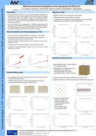
Experiments Ultrahigh strength of Dislocation-free Ni3Al nanocubes, Robert Maasset al. • Goal: study compressive strengths of dislocation-freeNi3Al nanocubes • Size-dependent ultrahigh strength (2-10 GPa) • Dislocation nucleation at free surfaces as a governing plasticity mechanism in nanosized crystals Slip traces of dislocations on the surface Strain “burst” (dislocation nucleation)
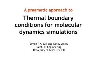
Research goal • Experimentsand finite elements analysis do not give us information on the underlying dislocation mechanisms. • In this research, we perform a molecular dynamics simulation, to obtain insights on the atomistic mechanismswhich dominate the deformation of Ni3Al nanocubes.
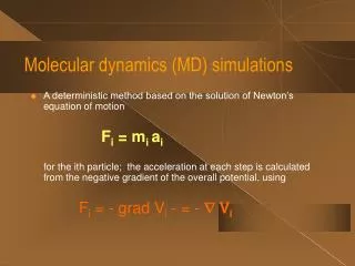
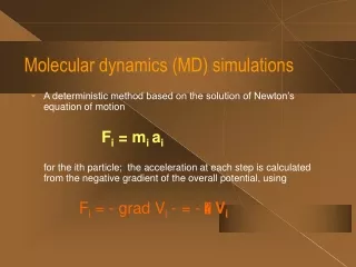
Molecular Dynamics simulation • Molecular Dynamics (MD) is a computational method to determine the trajectories of atoms in phase space according to Newton’s equations of motion (F=ma). • The forces acting on each atoms are derived from an interaction energy, which is calculated according to atom positions, using effective interatomic potentials. • We employ an Embedded Atoms Method potential (EAM), which is reliable for FCC metals, with a set of parameters calibrated by Purja Pun, G.P. & Mishin, Y. (REF: PurjaPun, G.P. and Mishin, Y.(2009) 'Development of an interatomic potential for the Ni-Al system', Philosophical Magazine, 89: 34, 3245 — 3267)
Step 1 – construct a Ni3Al lattice In order to examine the ability of the potential to describe dislocation properties we constructed an “infinite” (fully periodic) Ni3Al lattice with 360K atoms. 309 Å 1311 Å 10 Å A screw dislocation dipole was introduce into the computational cell on (111) slip planes, according to isotropic elastic displacements. Burgers vector
Step 1 – Visualizing dislocations • Atoms in dislocations are identified according to BOP (bond order parameters) • BOP– A set of symmetry parameters that defines the local symmetry in the lattice. For instance, the BOP of an atom in the perfect bulk is different from the one in the CSF. • We used Atomeye for visualization. CSF APB CSF dipole b
Step 2 - Calculate the dissociation widths Dissociation width calculation for one typical dipole Simulation results (MD and excel) APB converge to 7b (35 Å) CSF converge to 2b (10 Å)
Step 2 – Calculate the dissociation widths Width of planar faults follows from the energy balance between the faults energy and the elastic interaction forces between partial dislocations Analytical results (maple)
Step 3 - compression of nanoparticles • We constructed a Ni3Al nanocube (size 17.9x17.9 nm, 250k atoms) and compressed it with a virtual planar indenter (a repulsion force field which propagates at a constant rate towards the nanocube). 178.5 Å
Step 3 - compression of nanoparticles • The forces on the indenter are extracted from the simulation. • Stress & strain are calculated: • Traces of deformation twinning made by a glide of twinning dislocations can be observed on the surface. Nucleation at 5 GPa Elastic zone
What‘s next? • What’s next? • Improving techniques of visualize faults in alloys (intermetallics). • Analyzing the dislocations mechanisms of the deformed nanocube. • Using other interatomic potentials.