Download
1 / 19
190 likes | 315 Vues
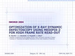
IWORID 2004. OPTIMIZATION OF X‑RAY DYNAMIC DEFECTOSCOPY USING MEDIPIX-2 FOR HIGH FRAME RATE READ-OUT D. Vavrik 1, 2 , J. Jakubek 2 , S. Pospisil 2 , J. Uher 2 1 Institute of Experimental and Applied Physics Czech Technical University in Prague

E N D
IWORID 2004 OPTIMIZATION OF X‑RAY DYNAMIC DEFECTOSCOPY USING MEDIPIX-2 FOR HIGH FRAME RATE READ-OUT D. Vavrik1, 2, J. Jakubek2, S. Pospisil2, J. Uher2 1 Institute of Experimental and Applied Physics Czech Technical University in Prague 2 Institute of Theoretical and Applied Mechanics of the Czech Academy of Sciences Glasgow, 25 - 29th July
Outline • X-ray Dynamic Defectoscopy • Recent status • Parameters influencing XRDD resolution • Tuning of selected parameters • Conclusions Glasgow, 25 - 29th July
Stressed Al specimen With prefabricated slit Hamamatsu rtg tube Region of interest Medipix detector The X-Ray Dynamic Defectoscopy • Standard X-ray defectoscopy is already widely used diagnostic method. • Stressed ductile materials (aluminum alloy for instance) are damaged by loading dependent generation and development of voids. • Using high performance semiconductor pixel detectors (Medipix) it is possible to observe time dependent (dynamic) structure changes in loaded material. => X-Ray Dynamic Defectoscopy Glasgow, 25 - 29th July
XRDD principles The XRDD measurement is based on attenuation of an X-ray beam passing through the specimen. This is proportional to an effective thickness reduction by the volume fraction of damage and by contraction. Loaded specimen Medipix detector attached to water cooling system Hamamatsu X-ray tube Experimental setup for XRDD Glasgow, 25 - 29th July
MEDIPIX-1 detector A single photon counting Medipix-2 chip is formed by 256x256 pixels of 55 µm pitch (14x14mm chip size). http://medipix.web.cern.ch/MEDIPIX/ Glasgow, 25 - 29th July
Recent status of our XRDD experiments • Still working in semi-static regime. Specimen is loaded gradually and the roentgenogram is taken at each loading level. • We reached 10 mm accuracy in measurement of the effective thickness reduction (along the X-ray beam direction) of 5 mm thick Al sample for 10x30sec exposures using Medipix-1 detector. • Such accuracy allows to measure material damage development. Developing of the damage zone in the loaded specimen Glasgow, 25 - 29th July
Analyzed parameters influencing XRDD resolution • Observation of time dependent processes require optimization of XRDD settings for minimization of exposure time with respect to required resolution. • Resolution of the XRDD method for thickness measurement depends on: • The attenuation of X-ray beam by the observed specimen and on the fraction of transmitted photons registered by the Medipix detector. • Spectrum of the X-ray tube at its actual voltage and current used. • The efficiency of the Medipix-2 device at the actual spectrum. • Flat field correction • It is necessary to pay attention to various hardening of X-ray beam due to various thickness of the observed object. • Standard flat field correction • Direct Thickness Calibration Glasgow, 25 - 29th July
X-ray tube Voltage and Current As a source of X-rays, we used a Hamamatsu microfocus X-ray source L8601 with focal spot size 5 m (tungsten anode). Maximal available power capacity of X-ray tube has been used for each operation point. Transmission of X-ray beam passed through Al plate was measured by the Medipix-2 detector at 10 voltage and current levels (see table on the right). Signal to noise ratio (SNR) has been estimated at each tube working point for each plate thickness (1-6 mm). These results served as a base for calculation of experimental time needed for required XRDD precision. Glasgow, 25 - 29th July
Measured transmission Error bars are defined by poisson law. Glasgow, 25 - 29th July
Error estimation for 100 sec exposure Glasgow, 25 - 29th July
Exposure time estimation Glasgow, 25 - 29th July
Standard flat field correction produced poor quality when thickness variations are significant (we observed 30% thickness reduction in our experiments). Flat field correction: Direct Thickness Calibration Thickness variations are too large => spectrum differs from pixel to pixel => standard flat field correction does not work. Method of Direct Thickness Calibration for Each Pixel has been used • Dependence of count rate on a absorber thickness is measured for each pixel (works for any material with equivalent attenuation). • Experimental data for unknown specimen are transform directly into thickness. Dependence of count rate on thickness of Al sample for two arbitrary detector pixels. Glasgow, 25 - 29th July
Comparison between standard flat field correction and Direct thickness callibration Standard flat field correction has been done using 2 mm thick standard. Glasgow, 25 - 29th July
Illustration of Direct Thickness Calibration Ground beetle Glasgow, 25 - 29th July
Standard flat field correction 1. Acquired image 2. Standard flat field correction Very bad result - unusable Glasgow, 25 - 29th July
Direct Thickness Calibration 2. Standard flat field correction 2. Direct Thickness Calibration Glasgow, 25 - 29th July
Conclusions • Direct calibration of each individual pixel value to thickness of the absorber is possible and gives very good results. • Time necessary for required XRDD thickness resolution of 1000 sec is still to long. We can reduce by: • Shorter distance between X-ray source and detector. • Use of superpixels (2x2 pixels for instance) for higher count of processed photons (it will reduce spatial resolution). • Reduction of sample thickness if it is possible. • Higher intensity of X-ray source (synchrotron X-ray source) if available. Glasgow, 25 - 29th July
Acknowledgement This work is carried out within the framework of the Medipix Collaboration based at CERN (see: www.cern.ch/medipix). This work was made possible by the Grants No. 106/00/D064 and No. 101/03/0731 from the Grant Agency of the Czech Republic. This work has been also partly supported by the Ministry of Education, Youth and Sports of the Czech Republic under Research Program MSM 210000018 and by the Czech Committee for Collaboration with CERN under a grant of Ministry of Industry and Trade of the Czech Republic Glasgow, 25 - 29th July
Illustration of attenuation equivalence for different materials Glasgow, 25 - 29th July