Integrating Imagery Remote Sensing for GIS Project Managers
680 likes | 810 Vues
This presentation by Timothy L. Haithcoat from the University of Missouri explores the integration of remote sensing technology in Geographic Information Systems (GIS) for project managers. It discusses the science of remote sensing, the importance of ground truth data, raster modeling, spatial resolution effects, and implications for project cost and analysis. Emphasis is placed on understanding the balance between data acquisition techniques and managing project scales effectively to enhance spatial data accuracy and utility in various applications.

Integrating Imagery Remote Sensing for GIS Project Managers
E N D
Presentation Transcript
Integrating ImageryRemote Sensing for GIS Project Managers Timothy L. Haithcoat University of Missouri GRC/MSDIS/ICREST
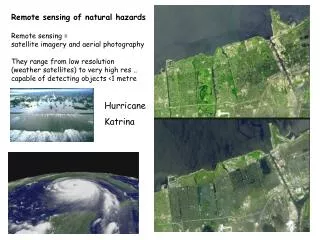
What is Remote Sensing? • The science and art of obtaining information about an object, area, or phenomenon through the analysis of data acquired by a device that is not in contact with it. • Remote sensing is a tool - not an end in itself
GENERALLY • Question on what the problem ‘is’ comes from detailed ground observation • Remote sensing comes in at where, howmuch, and how severe the problem is.
Considerations • Photograph scale is a function of terrain elevation - hence ortho-rectification needed • Geometry - ground control • Finer scales = higher costs & more photos • Photo-interpreter - hard to maintain consistency • Mental acuity + visual perception
Reference DataGROUND TRUTH • Collecting measurements or observations about the features being sensed • Two types - time critical / time stable • Three uses • Aid in analysis and interpretation of data • Calibrate sensor • Verify information extracted from image data
Raster Model • Divides the entire study area into a regular grid of cells in specific sequence • The conventional sequence is row by row from the top left corner • Each cell ( or picture element - PIXEL) contains a single value • Is space-filling since every location in the study area corresponds to a cell in the raster • One set of cells and associated values is a layer • There may be many layers in a database • Examples: soil type, elevation, land use, land cover • Tells what occurs everywhere - at each place in the area
Creating a Raster • Consider laying a grid over a land cover map • Create a raster by coding each cell with a value that represents the land cover type which appears in the majority of that cells area • When finished, every cell will have a coded value W W W G G water W W W G G W W W G G grass G G G G G F G G U U urban forest F F G U U
Influence of Spatial Resolution • Consider laying a coarser grid over our land cover map • Problem of mixed pixels or cells • Implications when landscape is broken up into fine pieces W G G water W G G grass F U U urban forest
Influence of Spatial Resolution • Consider laying a finer grid over our land cover map • Resolution needed to discriminate the smallest object to be mapped • Implications on file size and access times water grass urban forest
Zoom Scale Change of a 1”=400’ Scale Features Scale 1”=400’
Zoom Scale Change of a 1”=400’ Scale Features Scale 1”=200’
Zoom Scale Change of a 1”=400’ Scale Features Scale 1”=100’
Zoom Scale Change of a 1”=400’ Scale Features Scale 1”=50’
Zooming an Image... • Does not Change the Accuracy • Does not Change the Resolution • You merely enlarge or reduce your view of the images original Pixels
Having Said All that... What IS the Impact of Resolution? Same Scale Image Viewed with Different Resolutions...
Resolution 0.5’/pixel Scale 1”=50’
Resolution 1’/pixel Scale 1”=50’
Resolution 2’/pixel Scale 1”=50’
Resolution 4’/pixel Scale 1”=50’
Impact of Resolution • Spatial resolution at which the imagery is actually acquired plays a key role in determining what you can use this imagery for. • You can zoom in all you want but it can not change the resolution at which it was acquired!
Landsat 7 ETM+ 15 m SPOT 10 m Indian Remote Sensing (IRS) 5 m IKONOS 1 m
Landsat MSS 60 m Landsat ETM + 30 m Indian Remote Sensing 20 m IKONOS 4 m Positive Systems 0.7 m
Other Resolution Concepts • Spatial • Smallest resolution element • Areal coverage • Radiometric • Number of brightness values detected • Spectral • Number of bands • Bandwidth • Location of bands within the spectrum • Temporal • Frequency of revisit • Time of day
IKONOS 1M Pan vs DOQQ 1M Radiometric Resolution Comparison DOQQ IKONOS
Imagery as a Central Data Source • In the past, imagery and spatial data was often separate GIS Guys vs. Image Processing & Photogrammetry Guys • Recent developments in technology have moved these much closer and they will increasingly be closer.
Trends in Remote Sensing Systems • Continuity of established programs (Landsat, SPOT) • Higher spatial resolution • Wide-field monitoring sensors • Hyperspectral sensors (dozens to hundreds of bands) • Radar and Lidar • More commercial systems
What is Needed to Estimate Project Costs? Estimates of Project Area in Square Miles Estimates of Image Costs per Square Mile A Set of Business-based Assumptions Image Specifications
Mixing Alternate Scales • You can reduce the project costs by changing the projects scale requirements or by mixing scales. • This concept matches the appropriate scale to a corresponding subject area.
Basic Issues to Integration • What follows in the next few slides are examples of simple imagery integration issues that the GIS Project Manager will face.
Less area covered: with minimum strip of 11km x 11km Requires lots of time for processing: ex. Mosaicing Tones do not match properly because imagery was taken at different times Columbia metro area covered in two images (necessarily collected on different dates) Spatial Resolution: Limitations
Frequent revisit helps in easy update and more chances for acquiring cloud free data. Minimum cloud cover is 20 %. You have to pay extra money. PE: It can take many months to get cloud free data. Suggestion: Ordering the data between known cloud-free dates would help Cloud cover
352 IKONOS satellite allows to specify the specific image acquisition angle But, it will be treated as a nonstandard order and may result in a longer delivery time frame and additional surcharge Walnut Azimuth
The next series of slides will present a tool used to integrate legacy GIS vector information with newer and more accurate imagery data More Involved Integration Issues
Integrating ImageryThe Local Problem • Vector GIS data lineage may preclude direct integration with image data sets • Mapping pre-dates computers • Stand-alone system organized by tiles • Integration with other data – GPS • Huge investments in GIS data • Imagery can provide the accurate base map materials to meet these needs
Creating Image to Vector Linkages • Extracting the nodes from the image based road centerlines file • Building or acquiring a centerline vector file from within the current local GIS and building a node file from this source • Conducting a local-area search to establish the positional relationships between these two sets of nodes.