Download
1 / 33
330 likes | 514 Vues
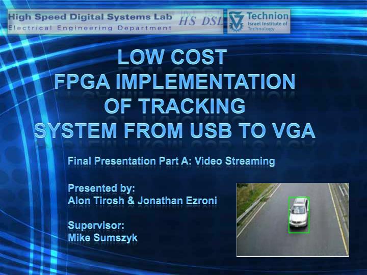
LOW COST FPGA IMPLEMENTATION OF TRACKING SYSTEM FROM USB TO VGA. Final Presentation Part A: Video Streaming. Presented by: Alon Tirosh & Jonathan Ezroni Supervisor: Mike Sumszyk. Project Goals. Get to know Quartus SoPC builder environment Stream Video

E N D
LOW COST FPGA IMPLEMENTATION OF TRACKING SYSTEM FROM USB TO VGA Final Presentation Part A: Video Streaming Presented by: AlonTirosh & Jonathan Ezroni Supervisor: Mike Sumszyk
Project Goals • Get to know • Quartus • SoPC builder environment • StreamVideo • Build foundation for part B - Tracking system
Project Stages • Configurethe system using SoPC builder • Createembeddedsoftware • Generatesystem input using USB • Displayvideo
USB Basics Device Host
Host • Detect Attachment/Removal • Manage Control flow • Manage Data Flow Device • Respond to Requests • Status • Data
Isochronous Transfer • High priority • Low latency • No Resend on Error
System Architecture DE2 Board Cyclone II Instruction memory Nios II Processor Avalon BUS VGA controller SRAM Controller DMA block USB Controller PC - USB VGA D/A SRAM Philips ISP1362 15 fps
Referenced Architecture • Tal Rath and EyalEnav • Configuration: • NIOS II USB • Jungo configuration • DE2 demonstrations
Our Design • Data flow inside the System • Input from file • Streaming format
Video Streamer 1 2 . . . Packet Number Packet Data 1 1022 38 Packets per frame USB
Packet Arrival Philips ISP1362 UBS 2.0 controller PC DMA Block NIOS Cyclone II SRAM DE2
Software [Iso Data Transfer] [USB Interrupt received] Start Tx & Rx IDLE Lock INT [Tx done Interrupt] [No Error]
ISO ISR • ISO Data Transfers • USB interrupt handler • USB interrupt handler TIMELINE Main Loop TIME [USB Int] ISR_Ep05Done Tx DMA ReadIsoEndpoint Rx DMA Tx Done Rx Done
Why DMA? • CPU can perform data transfers… … but then it won’t be available for anything else… • The DMA allows us to transfer data from one place to another without making use of the CPU.
Direct Memory Access • DMA receives: • Source • Destination • Amount of data to transfer
DMA USB INTERFACE DMA PC sends a packet System receives INT DMA starts transfer USB DATA PORT System awaits next INT Transfer finishes SRAM
SRAM VGA INTERFACE VGA SRAM
Host Access Collision DMA VGA SRAM
DMA VGA System with fifo Host Transmission done DMA streaming FIFO Reception done SRAM
USB Selected Design DMA DMA Block FIFO DMA VGA SRAM
Pixel Format • Data Bytes per packet = 1022 • Bytes per pixel = 2 • Pixel per packet = 1022/2 = 511
24 vs 16 bit RGB 24 bit RGB 16 bit RGB
Tools and Debug • Quartus II – Signal tap. • Model Sim– for design verification • Logic analyser • Nios II IDE • Hex Editor • Microsoft Visual Studio
Troubleshooting • Quartus • Version related issues • USB Drivers • Model Sim • Nios II IDE • SoPC builder environment
LogicAnalizer • Digital Scope • Memory
Memory considerations • 0.5 MB SRAM is not enough for possible extended image resolution (640x480). • 8 MB of SDRAM will be enough for: 160x120x3x3 = 172,800 Bytes which is the current plan.
2.Algorithm Motion image computation Mass center computation Prediction of next mass center (Kalman filter or more simple algorithm)