Advancements in Hybrid Rocket Design for Space Exploration
270 likes | 383 Vues
Project M.E.T.E.O.R focuses on developing a hybrid rocket powered by Nitrous Oxide and HTPB fuel to carry payloads to the edge of space. The immediate goal is to demonstrate the launch capabilities of the rocket, which will be elevated by weather balloons before propulsion into orbit. Long-term, the project aims to facilitate payload delivery to Near-Earth Objects (NEOs). With an emphasis on optimizing rocket design through innovative concepts and research into materials and thrust vectoring systems, the project strives to ensure successful missions into space.

Advancements in Hybrid Rocket Design for Space Exploration
E N D
Presentation Transcript
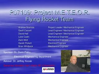
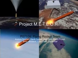
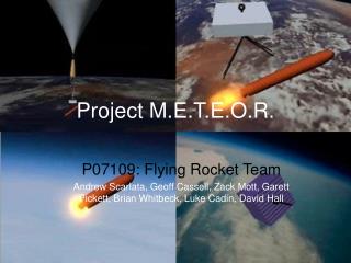
Project M.E.T.E.O.R. P07109: Flying Rocket Team Andrew Scarlata, Geoff Cassell, Zack Mott, Garett Pickett, Brian Whitbeck, Luke Cadin, David Hall
M.E.T.E.OS.R. Overview • Immediate goal is to prove ability to launch a hybrid rocket using Nitrous Oxide and HTPB carrying a small payload to the boundary of space. • Long-term goal is to launch payloads both into space and to land them on NEO’s. • Meteor rocket is carried to altitude by weather balloons, released, and propels itself into orbit.
Our Objectives • Responsible for integration of Steel Rocket and Guidance teams’ systems. • Optimized Fuel Grain, Combustion chamber, Nozzle and Injector designs. • Thrust Vectoring and guidance systems. • Research materials that satisfy the design requirements. • Design, Manufacture, Test and Launch Single Stage Rocket • Research shows that successful rockets adhere to a 1:10 structure to propellant ratio. The minimum requirement is 2:10.
Rocket Design Concepts Hot means Owwie! • Five designs • Classic • Chalice • Embedded Fuel Grain • Exterior Nitrous Oxide Tanks • Annular Nitrous Oxide Tank
Classic Concept • Constant radius dimensions determined by Fuel Grain • Advantages • Easy to manufacture • All subsystems can be contained within outer shell • Disadvantages • Extreme length requires excess weight • Guarantees custom Nitrous Tank
Micro IMU (Inertial Measurement Unit) Payload Electronics Helium Reservoir Composite Outer Shell (Possibly Aluminum Reinforced) Nitrous Oxide Tank Pre-Combustion Chamber HTPB Fuel Grain Post-Combustion Chamber Graphite Nozzle
Payload Pico-Satellite Micro IMU Provides serial digital outputs of tri-axial acceleration, rate of turn (gyro) and tri-axial magnetic field data. Electronics Avionics and Data Acquisition Helium Reservoir
Nitrous Oxide Tank (Liquid Fuel) Pre-Combustion Chamber Moldable Ceramic, acts also as an insulator for the composite shell HTPB Fuel Grain (Solid Fuel)
HTPB Fuel Grain (Solid Fuel) Post-Combustion Chamber Moldable Ceramic, acts also as an insulator for the composite shell Graphite Nozzle Currently replicates the steel rocket design
Chalice Concept • Dimensions determined by Nitrous Tank • Advantages • Reduced weight due to aspect ratio and variable radius • All subsystems contained within shell • Accommodates varied payload geometries • Potential for off the shelf Nitrous tank • Disadvantages • Complex geometries complicate production
Micro IMU (Inertial Measurement Unit) Payload Electronics Helium Reservoir Composite Outer Shell (Aluminum Inner Reinforced) Nitrous Oxide Tank Pre-Combustion Chamber HTPB Fuel Grain Post-Combustion Chamber Graphite Nozzle
Micro IMU Payload Pico-Satellite Electronics Avionics and Data Acquisition Helium Reservoir
Nitrous Oxide Tank (Liquid Fuel) Pre-Combustion Chamber Combustor HTPB Fuel Grain (Solid Fuel)
HTPB Fuel Grain (Solid Fuel) Post-Combustion Chamber Graphite Nozzle – Replicates the steel rocket design
Embedded Fuel Grain • Dimensions determined by nitrous tank • Advantages • Reduced Pressure Differential surrounding fuel grain • Single tank forms main body surrounding engine assembly on all but nozzle side • Disadvantages • Complex structural design
Micro IMU (Inertial Measurement Unit) Payload Helium Reservoir Vessel Electronics Nitrous Oxide Tank Pre-Combustion Chamber Composite Outer Shell (Aluminum Inner Liner) Siphon Tube HTPB Fuel Grain Post-Combustion Chamber Graphite Nozzle
Micro IMU Payload Pico-Satellite Electronics Avionics and Data Acquisition Helium Reservoir
Nitrous Oxide Tank (Liquid Fuel) Pre-Combustion Chamber HTPB Fuel Grain (Solid Fuel)
Siphon Tube HTPB Fuel Grain (Solid Fuel) Post-CombustionChamber Graphite Nozzle Steel rocket replica
Other Concepts • External Nitrous Tanks • Four External tanks mount outside of main body, providing more compact rocket, but added cost. • Annular Nitrous Tank • Single tank mounts around main body, providing more structural strength but added weight and cost.
Material Concepts • Researched metal, ceramic and fibrous and honeycomb composite possibilities • Metals and ceramics are cheap, easy to manufacture, however are too heavy for this application by themselves. • Composites may not hold up to heat, pressure and acceleration stresses. • Solution may be hybrid: composite overwound aluminum.
Nitrous Oxide: Self Pressurization • Rely on self pressurizing characteristics of Nitrous Oxide(N20) to drive liquid N20 flow • Vapor pressure a very strong function of temperature • Atmospheric temperatures during balloon ascent as low as -57 degrees Celsius, will cool N20 • Clear need to carefully regulate temperature pressure, likely target range between 20 and 30 Celsius (734 to 916 psi).
Self Pressurization • Furthermore, critical temperature of N20 is 36.42 Celsius; past the critical point, most thrust will be lost • Would need to develop accurate heat transfer model to insure tank would be kept at proper temperature • Insulation and heater will be required
Helium Gas Pressurization • Would use separate tank of Helium at high pressure (regulated to desired pressure) to pressurize N20 tank • Helium pressure will be much less temperature sensitive and will be able to supply pressure reliably that we need • Provide constant pressure (and hence thrust) throughout entire burn time • Will add weight to system, which is at a premium
Schedule for rest of SD1 Hot means Owwie! Week 6: Intense revision of concept for final selection, further material research/selection, further modeling of concept. Week 7: Start basic system design, begin risk and engineering analysis, continued modeling of design. Week 8: Continue FEA analysis, complete proof of concept, begin material purchasing, complete design modeling. Week 9: Completion of basic system design, prepare for Design Review, continue material purchasing. Week 10: Plan for SD2, continuation of system design, material purchasing.
Questions? Thank You